
|
|
Forum Index : Solar : Why can�t YOU make hot water with PV?
| Author | Message | ||||
| hotwater Senior Member Joined: 29/08/2017 Location: United StatesPosts: 120 |
It's not rocket science. I've done it many ways. The best is directly off the PV array voltage. It will take whatever power the charge controller doesn't. The circuits are simple, charge a capacitor bank and pulse the heating element till the voltage drops a little. Then let the capacitors recharge. If you look at it one section at a time it is easier to understand. Only about a half dozen working parts. I think this is the easiest and it can use existing mechanical thermostat (explained later). This is not complete schematic. You have to start somewhere. Asked away, I can't read minds. 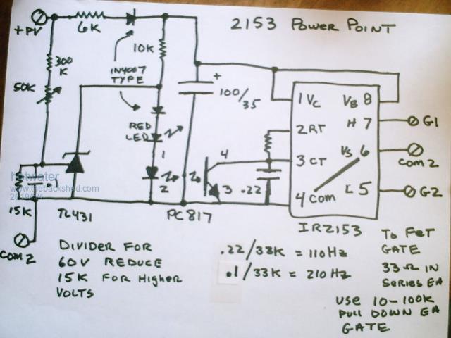 Please only ask ONLY ONE specific question in a post. It is important that each answer be fully understood before moving on to the next question. This is the KAHN method of learning. If you break the project into parts it is easier to understand. This is a very easy project if approached this way. |
||||
| Tinker Guru Joined: 07/11/2007 Location: AustraliaPosts: 1904 |
While I do not need such a device at this stage I studied your drawing out of interest. You could have done a lot better by providing a link , for that IR2153 self oscillating half bridge driver. Having never used that chip I had no idea what it does, the datasheet explained that. You could also have included the high voltage switching part of this project. To me, that would make understanding it a lot easier. As it is, I got the gist eventually from the data sheet. A part schematic may be fine for you but to provide bite size info to others is not the best way to pass on information for a simple project like this. As you say, "its not rocket science", so trust us to understand the full picture if you care to provide it. Klaus |
||||
LadyN Guru Joined: 26/01/2019 Location: United StatesPosts: 408 |
Thank you hotwater for posting the schematic and creating a new thread to start discussion. Thank you Tinker for throwing your hat in the ring. As Dave and I have shared before, understanding the full picture would be very very important to understand these smaller bits However, since I have been following these posts with much interest, I will share my thoughts and welcome all input: Right, so does the modified 72V buck convertor fit on somewhere alongside this system in the more complete schematic? At this point you don't have to provide detailed schematics of each and every block - instead a block diagram that gives us an idea of the overall system will be good enough. Coupled with the RC snubber circuit this is really an ingenious design! 2 Questions (+1 above) instead of the one you requested: 1. Is the capacitor marked "100/35" alongside the PC817 a 100uF/35V rated capacitor? 2. Is the PC817 active high? (if the LED shines, the phototransistor conducts, otherwise floats) So let me try and see if I understand this design: Starting from the left (i/p) and moving to the right (o/p): The resistor divider in series splits the 60V between 2.47V - 2.86V depending on the wiper position and the actual PV voltage (60 * 15)/(365) = 2.4657534246575343 (60 * 15)/(315) = 2.857142857142857 This is Vref of the TL431 set up to shunt/draw away current from the PC817 photodiode when the PV voltage rises ABOVE the setpoint using the wiper. The PC817 photodiode exploits the CT pin of the IR2153 that doubles as an active low shutdown pin (the IR2153 shuts down when CT is brought low). So, when the PV voltage rises ABOVE the setpoint using the wiper, the TL431 shunts current away from the PC817 photodiode, turning the IR2153 on. Conversely, when the PV voltage falls below the setpoint using the wiper, the PC817 photodiode shines, the phototransistor shorts CT to GND, turning the IR2153 off. Now the TL431 works upto 36V, so we have to use a 6k-10k resistor divider to drop the ~60V PV voltage to around that I will post my working of how the resistor divider drops voltage to around 35V in a separate post and hence the rest of the circuit works off that. The 16k resistor also limits the current through the diodes to: 60/16k = 3.75mA Please let me know if this is all absolutely correct. |
||||
| hotwater Senior Member Joined: 29/08/2017 Location: United StatesPosts: 120 |
The IR2153 has internal zener regulation at about 15V. That is the reason these can be self powered up to 600V using only a single voltage dropping resistor. The zener will easily sink 15ma, more than enough to power the the TL431. the 2143 also has a low voltage drop out that prevents driving the FET in a linear region. The opto isolator will still have enough current to hold it in a turn off condition even below the LVDO. PC 817 is only 3 cents so I use it because of that higher 1V. It would also allow you to operate it remotely without a current loop. I've used just a FET or transistor. Optos are found in just about any old wall wart or consumer electronics as well as TL431. No need to spens a lot of money. THt TL431 in full saturation doesn't get much below 2V. The PC817 opto LED turns on with just about 1 volt. The red LED, besides being the inhibit indicator, acts as a 1.7V zener. An added diode in series increases that voltage a little more and insures the opto fully turns off. 1V opto + 1.7V LED + .6V diode gives a little more than 3V. The TL431 has to pull down more than that in order for the 2143 to start oscillating and it is deciding every half cycle whether to turn on. Two FET are driven independently but in parallel. Each will see the max current of the element. As the duty is nearly 50% each will dissipate half the heat. In reality, at low power one FET will operate more than the other. There can be reasons to drive each heater element separately. The thermostat switch is not really a RC network. A 400 ohm or more resistor is placed across the switch. When open, the heater control operates as a shunt regulator keeping the capacitors at the fixed power point voltage. The resistor across the switch only has to be a low enough resistance to power the module which is only about a watt. So, the switch never sees more than the open circuit panel array voltage minus the set voltage. As the voltage drops less than a volt on the capacitor bank the heating element almost immediately turns off. As the capacitor bank is nearly fully charged the turn on surge current. This circuit easily works to a little over 100V. 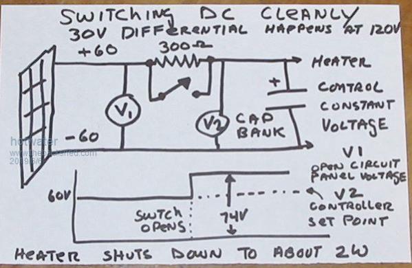 Providing links is just something I will never do unless it is something obscure. I don't waste my time with people who are too lazy to do a google search. They will never build anything. I put as much on a page as can be done without losing clarity. Anyone wanting to CAD this up and make circuit boards is free to do so. I'm just not interested in doing that. |
||||
| LadyN Guru Joined: 26/01/2019 Location: United StatesPosts: 408 |
hotwater, Thank you for providing that information but those details are a bit down the line. We are a bit behind from where you would like us to be at. At this very moment, I would rather appreciate: 1. A block diagram of your system - so we can figure out where this sits. You might have a water heater with multiple elements but our house has one with two and the top one I will have to keep on AC for those days when we wont have sun, so I will be driving only the lower element off PV. Others might have similar differences in implementation 2. Did you get a chance to read my post above - did I understand the circuit properly? 3. Are my calculations absolutely correct? If not, please mention where the errors are I am not only asking for myself but I hope this to be a guide for anyone who lacks a deep and intuitive understanding of the components - they can read what I have written and understand in details how it works, so my writeup being correct is very important. |
||||
| The Back Shed's forum code is written, and hosted, in Australia. | © JAQ Software 2026 |
