
|
|
Forum Index : Solar : Ultra Basic Picaxe PV Charge Controller
| Author | Message | ||||
| Solar Mike Guru Joined: 08/02/2015 Location: New ZealandPosts: 1162 |
Is it possible to build a MPPT PV Charge Controller using a Picaxe 8pin CPU. I have always wanted to have a go at implementing this ultra basic type of design, using minimal CPU control IO. Spec is up to 200 volts input, 40 amps max output, with any battery voltage between 12 and 100 Volts, fit on a 100 x 100 1oz copper PCB and no fancy external plug in modular components; and most importantly only use an 8 pin CPU. Here's my attempt: 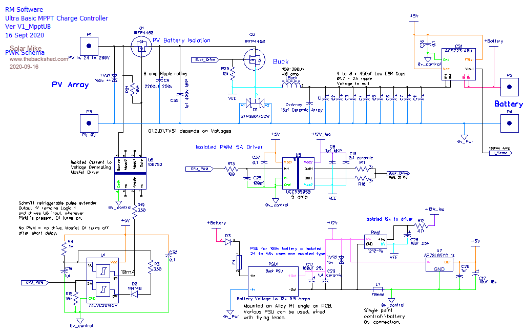 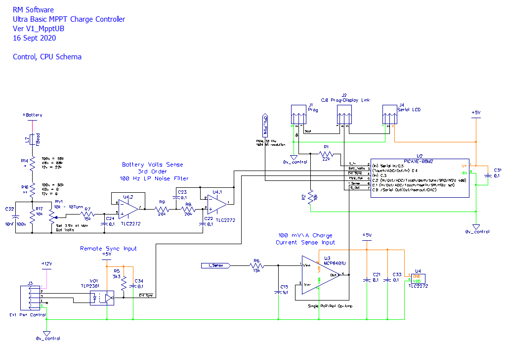 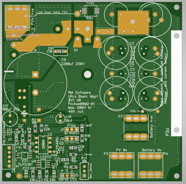 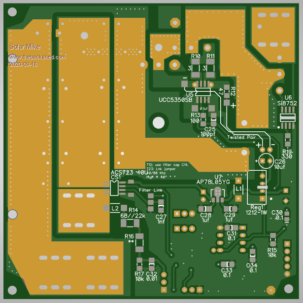 More later on how it works... Edit: Couple of items missing on PCB, will add them and update. Cheers Mike Edited 2020-09-16 23:02 by Solar Mike |
||||
| greybeard Senior Member Joined: 04/01/2010 Location: AustraliaPosts: 172 |
Subject has been raised on the PicAxe forum several times and basically the PicAxe doesn't have a fine enough PWM resolution to control an MPPT charger. |
||||
| Solar Mike Guru Joined: 08/02/2015 Location: New ZealandPosts: 1162 |
Did read that some time ago, think author was using in context of a fly-back inverter control, totally different scenario. 1024 bits of resolution is quite ok for a battery charger, gives approx 50mV resolution for 50V battery, even my Lifepo4 batteries don't require that amount of precision for accurate charging. Cheers Mike |
||||
| Solar Mike Guru Joined: 08/02/2015 Location: New ZealandPosts: 1162 |
Fixed a couple of issues on the pcb, this is one of the reasons for posting, looking at the layout and schematic from a different perspective - review; allows finding potential issues. No changes to the schematic, new layout below: 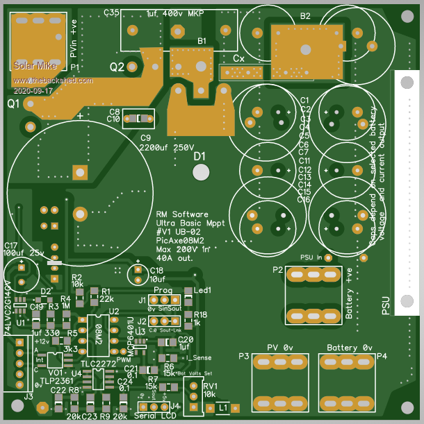 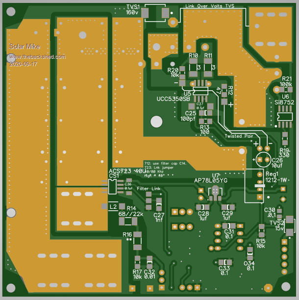 Few notes on the design: The 8 pin Picaxe has 1 pwm output, 2 analog ADC inputs, 2 digital inputs one of which is used when programming and 1 digital output also used when programming; these can be disabled by the running program and used as general IO. The 1024 bit PWM resolution @32Khz will be fine in this application. Aside from the PWM output, the bare minimum we need for control is to measure the output battery volts and charge current, that uses up the 2 ADC inputs. Cannot measure the PV voltage, will have to improvise using software to determine PV is present. Looking at the PWR schema, the PV input is isolated from the battery when not charging by Q1; this mosfet is turned on whenever PWM is present by voltage generating driver Si8752. The Si8752 is an opto coupled device and creates an isolated output voltage source that can turn on a power mosfet - slowly, several mili-seconds as the gate capacitance charges up. Slow is fine here as the mosfet will be fully on whilst charging, off when not. Power lost as a switch will be up to 40A^2 * 0.0025R = 4 watts. U1 a dual schmitt trigger inverter gate is used here as a re-triggering pulse extender, any PWM input rapidly discharges C19, causing the 1Y output to remain high whenever PWM is present, these IC's can output 30mA and the 1Y output drives 10mA into the opto driver. One less IO required. Buck conversion is by Q2 and schottky dual diode D1, gate drive supplied by U5, a UCC5350SB isolated 5 amp driver. Isolated 12V power for the driver supplied by a generic 1212-1W 4 pin PSU. The driver chip has 2 schmitt inputs, 1 of which is used, other turned on by shorting to 0V; the R13\C25 components act as a high freq noise filter. Buck inductor should be of a high value to keep the ripple current down below 5 - 6 amps, want to aim for 15 to 20% ripple current, so the 40 amp max output can be achieved with minimal capacitance. I will be using these Iron Powder E220-52 Cores as a starting point. Charge current sampled by a ACS723U chip, these output 100mV\Amp. A rail to rail input\output op-amp buffers the signal via a 10 Hz simple filter; the CPU can sample this to create a running average. For MPPT operation, going for max charge current is a simple way of doing it, after all we are attempting to maximize the current into the battery under all solar PV variations. Battery voltage is sampled via a 3rd order bessel low pass filter to get rid of the noise hash and fed to CPU ADC C.4. Software will limit max battery voltage set by 10T pot RV1 referenced to the 5V supply. The remote sync input I though might be useful in the future to connect to the BMS for current control, or to another charger, so multiple chargers can be paralleled with one device acting as a master, using a simple serial protocol; or as a generic switched input. Everything is dependent on the software, it will be fun writing it, will try to keep it as basic as possible. Will update results here. Cheers Mike |
||||
| Solar Mike Guru Joined: 08/02/2015 Location: New ZealandPosts: 1162 |
Before I send this lot of designs to be made, decided to also create a variation using a CPU with a few more IO pins, this allows some 10 turn pots for setting voltage levels and leds on a detachable cut-out to show charge status; uses the driver board from previous designs for a more optimum layout. 100 x 152mm PCB. 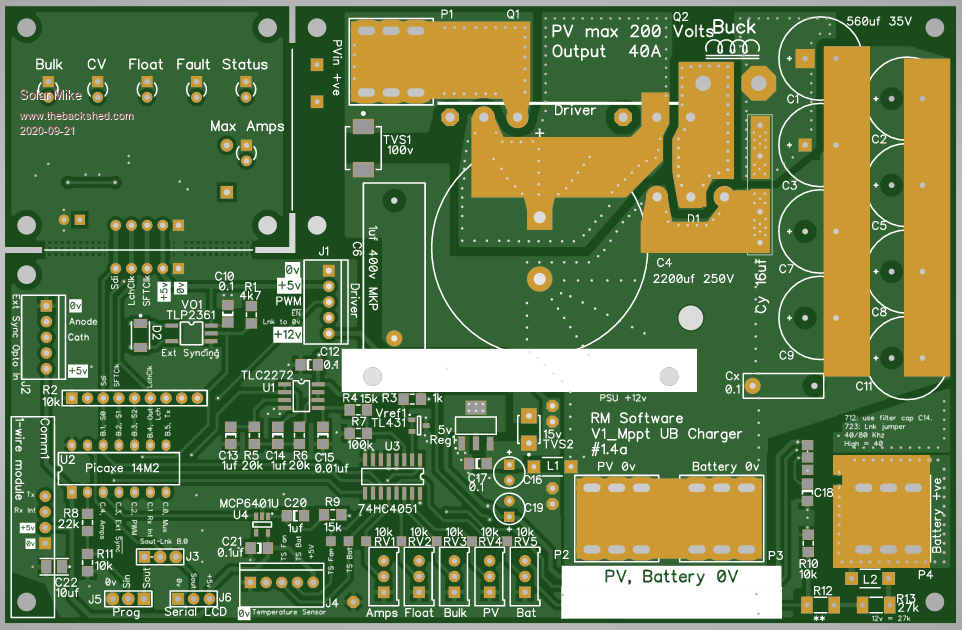 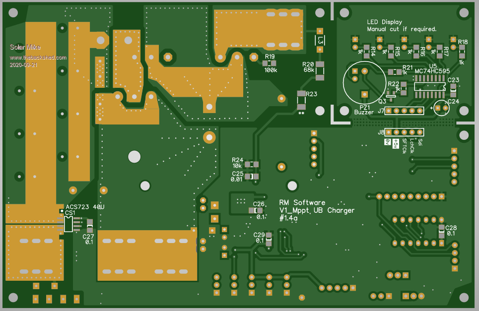 Cheers Mike |
||||
| Solar Mike Guru Joined: 08/02/2015 Location: New ZealandPosts: 1162 |
Schematics for the above: 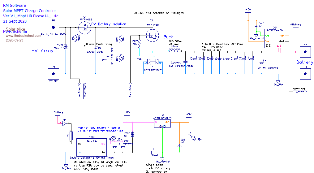 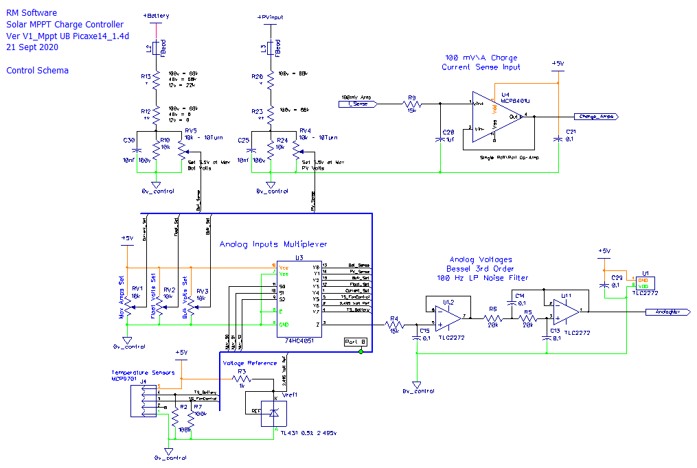 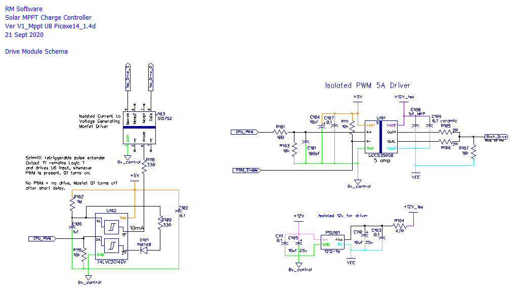 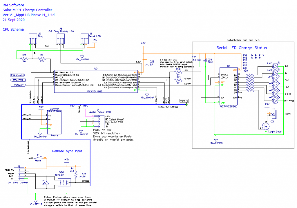 Cheers Mike |
||||
| Solar Mike Guru Joined: 08/02/2015 Location: New ZealandPosts: 1162 |
Its been awhile since I reported progress on this design, the first design using the PicAxe 08M2 has been built and software written. No errors on the pcb which is great; Here are some photo's. Bare PCB: 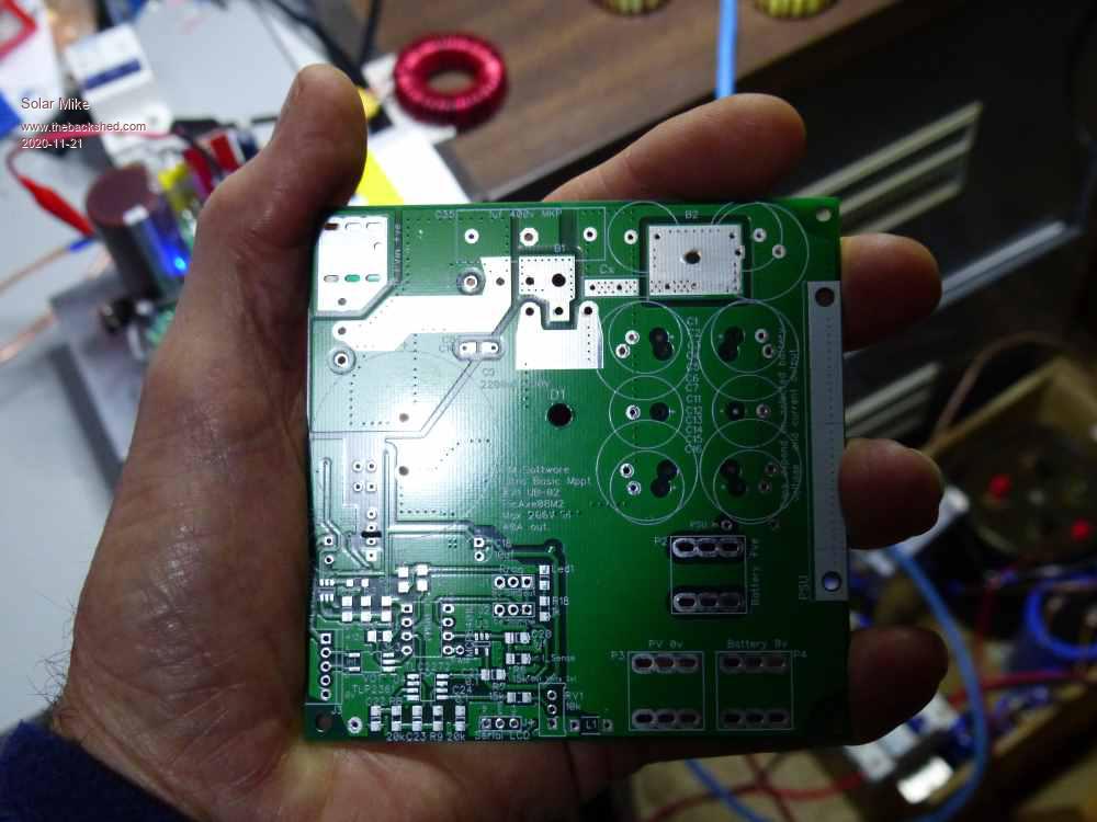 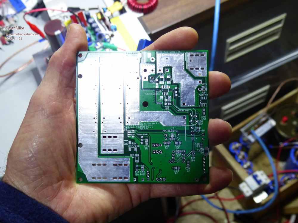 Populated showing input mosfet. Notice the 5mm^2 copper wire soldered to pcb, as the prototype is only 1oz copper 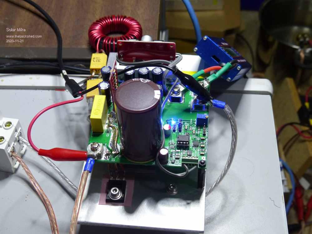 Closeup of top half, Big cap is 3300uf 160v, smaller ones on output are 8 x 470uf 35v @1.8amp ripple rating, there are too many here will take some off and re-test. The tall red pcb has an array of 20 x 1uf 100V smd ceramics mounted where the buck coil connects to the +ve out. The 12v DC power supply module is mounted on RHS on a scrap of alloy, its one of those buck/boost types so will output 12v from any input from 6 to 32v, 5v regulator is on the main board. 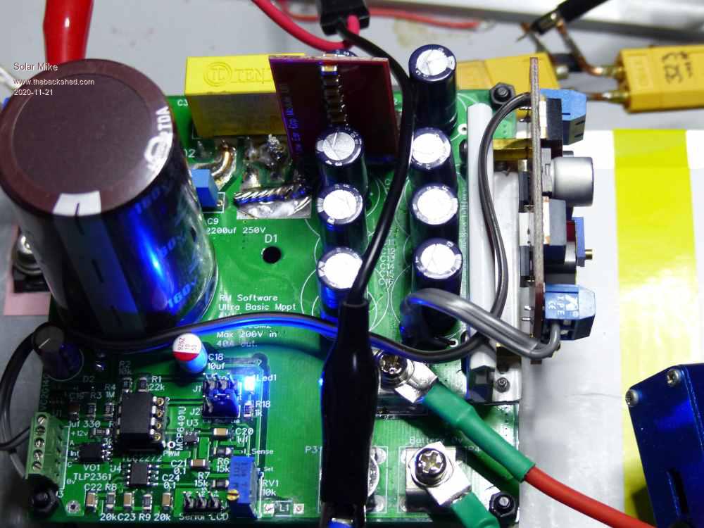 Selection of buck inductors, have connected via XT60 plugs and sockets for ease of swapping out. The square ECore is a Iron Powder E220-52, 43 turns of 4 strands 1.2mm dia wire, 186uH, Big Yellow with black leads Micrometals T200-26B, 44T same 4 strands 262uH, other yellow is T200-52B only 2 strands 327uH, Green is T200-52B with 26T 2mm dia wire 100uH, one connected to pcb under test is one of those sendust 56mm AS125 cores fully wound with 2mm dia wire, 323uH. They all gave very good results near the 12A testing so far. 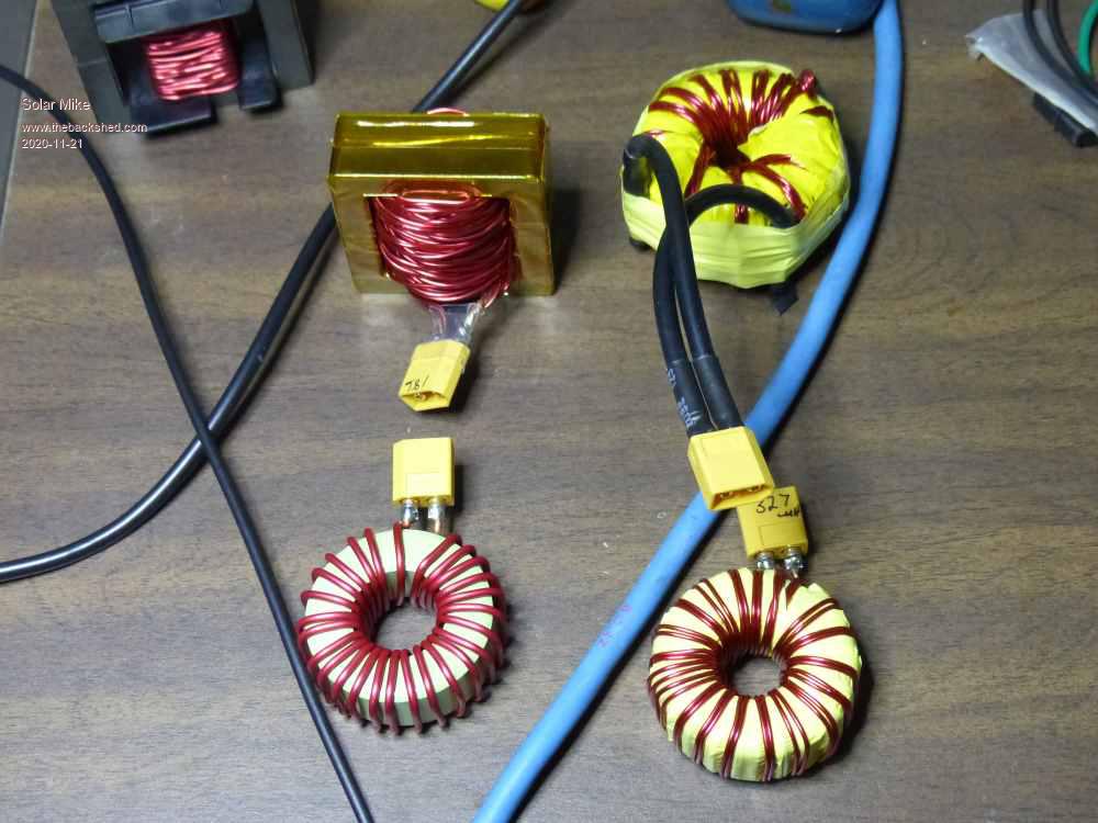 Under test with 11 - 12 amps to 12Volt lead battery and load sitting in a bucket of water, I need to make another load to test it at 20+ amps. The isolated hand held storage scope shows the AC current waveform through the buck inductor, I'm using a precision 0.01 ohm smd 5W resistor in series with the coil for the scope probe sense. The ac current @12 amps DC was 2 amps. Others at 12A 100uH 3A, 262uH 1.4A, 327 1.3A, ECore 1.3A Input voltage for testing was 30V psu with variable constant current setting, the higher the voltage the more inductance is required. Have used an IRFP4568 (150v 5mR) in the input and a IRFP4668 (200V 8mR) as buck switch, and a 180v dual Schottky. I want to test on a 50V battery with 130V input, thus current mosfets used. This design will be used on a number of 12V and 24V batteries 15-20A max so would be more efficient to use lower voltage lower R mosfets. At 12A efficiency is 92%, the mosfets are bolted to a 5mm alloy plate with a small finned HS, which won't be doing anything sitting upside down on my bench, after an hour @12A it barely gets warm, The main input cap is warm approx 35c, nothing else on the pcb gets warm. Inductors except the 100uH are just warm at about 30c. 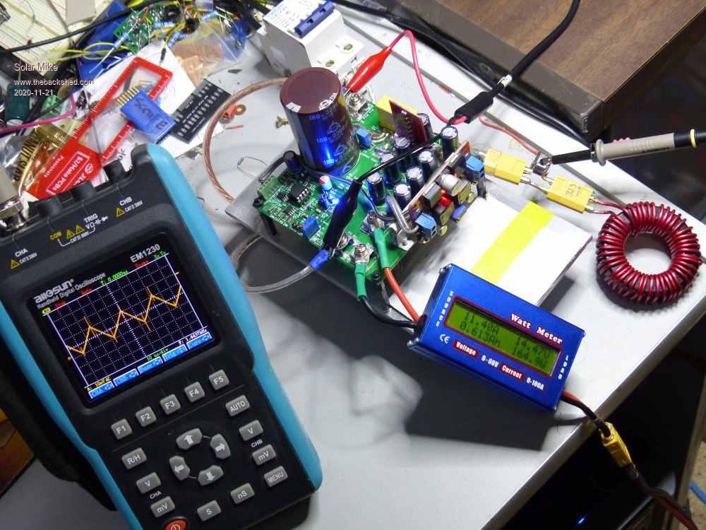 Will post the code on the PicAxe forum, current based mppt algorithm works pretty well, took awhile to sort out, connected it to a low voltage 16Vmp 150W panel on the roof this afternoon in the dying hour of not much sun, tracked quite well; PWM is 32Khz 10bit resolution. More testing tomorrow... Cheers Mike |
||||
| Warpspeed Guru Joined: 09/08/2007 Location: AustraliaPosts: 4406 |
I think going to the larger PicAxe is a wise move, opens up a whole lot of possibilities. Ten bit resolution should be plenty with a buck regulator, as it only needs to control the voltage ratio, the current will take care of itself, so less control range is needed. Flyback topology is a very bad idea for this type of application for many different reasons, rather surprised anyone is suggesting it. Excellent work Mike as usual, a very nice neat project. Cheers, �Tony. |
||||
| Solar Mike Guru Joined: 08/02/2015 Location: New ZealandPosts: 1162 |
Agreed, 8 pins is very limiting, but seems to work pretty well, to display any data to the outside world requires a 38400 baud serial display, which I don't have; would have to use another picaxe or an arduino as a serial port display. Where these are going, just a simple blinking led will suffice as a charge state indicator. Now will try to blow it up with > 20 amps through it.. Input cap may get too hot, really for higher pulse currents should use several to lower the esr and distribute the heat. Code has been posted on the active Picaxe Forum. Cheers Mike Edited 2020-11-22 13:26 by Solar Mike |
||||
| Davo99 Guru Joined: 03/06/2019 Location: AustraliaPosts: 1584 |
Your Idea of Ultra basic and mine differ about as much as our electronic abilities! :0) Great work! |
||||
| Solar Mike Guru Joined: 08/02/2015 Location: New ZealandPosts: 1162 |
"Ultra Basic" is somewhat of a pun, in that the picaxe cpu used here has only 8 pins, its programmed in a simplistic version of Basic and uses a minimal current controlled mppt tracking method. The schematic maybe more complex, but no more than required to be reliable. Hey its somewhat sunny outside today, time to see if I can blow it up. Cheers Mike |
||||
| Solar Mike Guru Joined: 08/02/2015 Location: New ZealandPosts: 1162 |
Well haven't managed to blow it up yet with 20-22 amp loads for an hour. Altered the software to allow loads above 20 amps and added another hot water element 10A load @12V to give a total of 20A + the battery charge rate. Changed the inductor to T200-26B with 26 turns 2mm dia wire, note this is a bit light should be 2 wires not 1, so copper losses are higher than expected. Heatsink gets a little warmer than previous, certainly < 40c, input cap gets approx 45c (its 105c rated) nothing else on the pcb really changes temperature, the output caps not even warm, the inductor as expected gets to 45c odd with the light gauge wire. Inductor AC ripple is now 4A or 20% ripple as per design for 26 turns. Input voltage remains at 30V, so will work ok on a 300W panel. Efficiency is 90% @20 amps and 30 volts input, with a PWM duty cycle of approx 50%, the higher voltage mosfets currently used would be more efficient if lower voltage types used if it was going to just charge a 12v battery. Calculations show the above inductor will work over the design spec of 35 amps ok without saturation, if the thicker wire is used, input voltages up to 61vmp (2 series panels) will also work, however the input cap probably would get too hot and have to be uprated to a lower esr type. Last test, I tried opening the output circuit breaker to the battery and @20A load to see what would happen to the sudden unloaded output voltage, it should rise; and did to 32V before the software shut down the pwm, no drama, did it twice to make sure. So quite pleased, works as designed; I will be building a number of them for 12v small batteries 100W or so panel and a 24v version for my UPS that I have rebuilt with Lifepo4 batteries. Will make up the other version next using 14M2 CPU. Cheers Mike |
||||
| Warpspeed Guru Joined: 09/08/2007 Location: AustraliaPosts: 4406 |
A very satisfactory result Mike, well done ! Cheers, �Tony. |
||||
| nickskethisniks Guru Joined: 17/10/2017 Location: BelgiumPosts: 462 |
Verry nice result! Clever way to test those inductors on a fast way! |
||||
| Solar Mike Guru Joined: 08/02/2015 Location: New ZealandPosts: 1162 |
Update: 08M2 version, software has been modified somewhat and been in various stages of test over the past few weeks, mppt code now works much better than my previous attempt. Testing on a 300W panel roof mounted, tracks in all light conditions from full sun, down to fractions of an amp at near dusk. Using a PSU with current limiting to simulate a PV panel 20A continuous is fine, nothing over heats, 30A would be the top end for the inductor I'm using, would need thicker wire; 40A would be the limit of this design. Current code and gerber files attached. Have a good Christmas all. V1_MPPT_UB_08M_2.zip Gerbers_UB.zip Cheers Mike |
||||
| nickskethisniks Guru Joined: 17/10/2017 Location: BelgiumPosts: 462 |
Hi Mike, Would the ucc5350sb be usable at 100% dutycycle, I see it uses some kind of capacitive coupling between in and output? I'm going to try some components in my next pcb designs like the SI8752, allways interesting to see your developments to get to know some new components. thanks |
||||
| Solar Mike Guru Joined: 08/02/2015 Location: New ZealandPosts: 1162 |
Will work fine at 100% duty (driving mosfets) as the spec on the device is for peak current loads of a mosfet gate, capacitive isolation coupling is logic compatible. Note the layout required to heatsink the device from the photo's, wide pcb traces to conduct heat away via the pin connections. On the little 08M2 board, chip gets barely warm with finger test. Cheers Mike |
||||
| The Back Shed's forum code is written, and hosted, in Australia. | © JAQ Software 2025 |
