
|
|
Forum Index : Solar : PV Powered Pump Controller
| Author | Message | ||||
| Solar Mike Guru Joined: 08/02/2015 Location: New ZealandPosts: 1204 |
I need something to startup our solar powered water pumps in the mornings as the sun come out. The long life magnetic drive pumps will be direct connected to a PV panel approx 50 - 180W and run continuously as long as the sun is shining, some run off 24v and others 12v dc; each voltage type has its own panel. Problem is at low light levels the panel cannot supply the starting current to get them running and will sit for some time in a stalled state drawing current in one winding rather than being shared, so its not good for the pump. There are a number of simple solutions out there on the net, using a comparator and a bank of electro's, the higher current devices are expensive and dont have any timing features, or the range of voltages, so its easier for me to just quickly throw something together and send off the gerbers along with a bunch of other boards. Here is the schema for a simple design using a Picaxe 08M2 for pump control, basically the cpu looks at the capacitor voltage and when its above a set value turns on the mosfet; if the voltage due to the loading falls away below another set point, then the mosfet is turned off, there will be some delay prior to turning back on, as these pumps have multiphase controllers built into them that spin a magnet inside the impellor; so cannot be fast pwm controlled. Will pickup any errors when the pcb is designed. 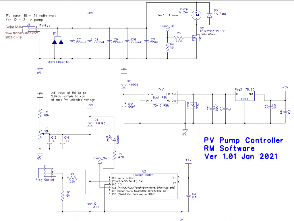 Cheers Mike |
||||
| bob.steel Senior Member Joined: 27/02/2020 Location: AustraliaPosts: 188 |
Following . In fact this could be used to turn anything on dependent on set on and off voltages. I like it. |
||||
| InPhase Senior Member Joined: 15/12/2020 Location: United StatesPosts: 178 |
Why not use a "linear current booster" to get the pumps started at lower PV voltages? This way you get more usable power. Waiting to turn the pump on is burning valuable sunshine. |
||||
| Solar Mike Guru Joined: 08/02/2015 Location: New ZealandPosts: 1204 |
You mean an adaptive buck converter with an altered feedback arrangement to provide a lower voltage but higher current to the motor circuitry, thus enabling the motor to start up?. Yes that would work and are available off the shelf (at a cost), but as I require several of these, the DIY aspect and cost savings win out here in building a more simple less complicated circuit to achieve similar results. The PV panels output are way higher than the pumps, so a simple current dump startup works well here. Cheers Mike |
||||
| Solar Mike Guru Joined: 08/02/2015 Location: New ZealandPosts: 1204 |
Yes it could I guess, the smd mounted switch mosfet used here has a voltage rating of 100v and >40 amps with an on resistance of 14mR, the pcb copper acts as the heatsink, limiting the design to max 15 amps. Will post pcb soon. Mike |
||||
| InPhase Senior Member Joined: 15/12/2020 Location: United StatesPosts: 178 |
Yep just like that. How about a DIY circuit along those lines? I don't really knows what they're doing internally. I just assume it's a buck regulator of some kind. |
||||
| Solar Mike Guru Joined: 08/02/2015 Location: New ZealandPosts: 1204 |
Perhaps a standard PV MPPT controller like the 08M2 version from an earlier post could be utilized here with a change of software to allow it to maximize current above a preset minimum output voltage, then as the pump started the voltage could be increased up to the pumps standard working value. Cheers Mike |
||||
| Solar Mike Guru Joined: 08/02/2015 Location: New ZealandPosts: 1204 |
Completed PCB and latest schematic, pcb is 100 x 100mm. 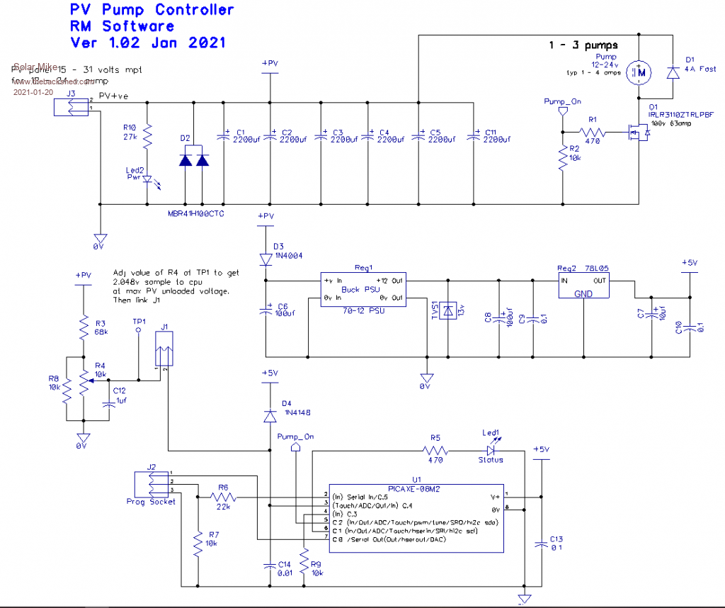 Top: 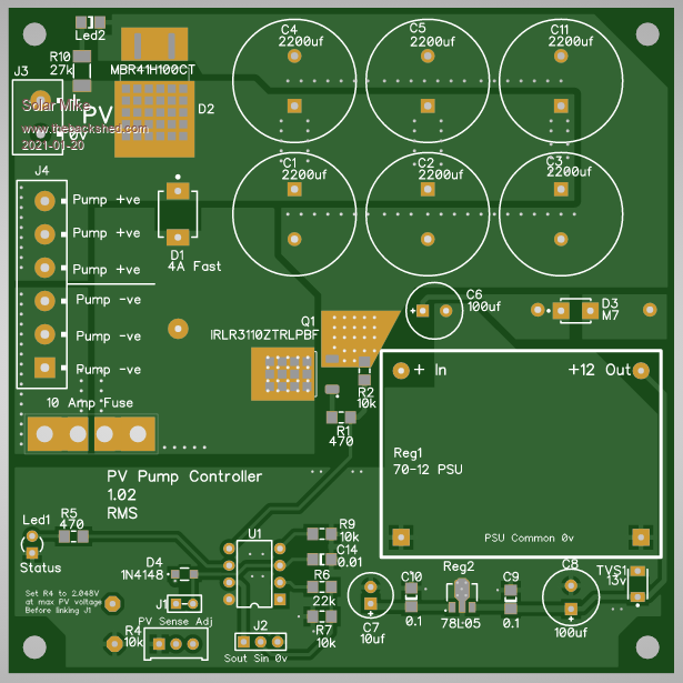 Bottom: 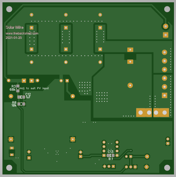 Anyone wants the gerbers, send me a post and I will email them to you. Cheers Mike |
||||
| bob.steel Senior Member Joined: 27/02/2020 Location: AustraliaPosts: 188 |
I'd like to get what files I need to open this in Kicad if possible . I'm trying to learn it and this would push me to learn. Just a thought though. I use a $14 voltage controlled relay to interfere with my charge controller because I can't trust it . Ill link the relay below . Its set to switch the MPPT charger on when the battery gets down to 25v and off when it get up to 27v. The voltage controlled relay unit runs on 8v to 34v so maybe with a small buck converter attached it would run it from the solar panel. It has many modes of operation and can be set the opposite way to come on at 27v and switch off at 25. Put in the negative PV line it would only allow a current when the voltage reaches 27v or whatever you set it at. Problem with the one I link below is its a 5v relay and 10 Amp contacts .I got around that with a truck relay driven at 24 volts which can do 30 amps.One relay driving the other.There will be other ways as well. Voltage relay switch Edited 2021-01-24 06:54 by bob.steel |
||||
| pollenface Regular Member Joined: 01/09/2020 Location: AustraliaPosts: 49 |
Why can't you trust your charge controller? Off grid man caver |
||||
| Solar Mike Guru Joined: 08/02/2015 Location: New ZealandPosts: 1204 |
What other cad systems can you import, I don't use Kicad. Those other voltage switches don't have the features that I require in this application. Cheers Mike |
||||
| bob.steel Senior Member Joined: 27/02/2020 Location: AustraliaPosts: 188 |
Well I joined Eagle too but I don't like their approach much . Can try it though .What do you use? |
||||
| Solar Mike Guru Joined: 08/02/2015 Location: New ZealandPosts: 1204 |
Sorry you misinterpret, what other formats will your cad (kicad) package import. I can export in DXF, Eagle board, P-Cad ASCII, PADs PCB ASCII 2005. If Kicad will import one of those, then I can send you the file. Cheers Mike |
||||
| bob.steel Senior Member Joined: 27/02/2020 Location: AustraliaPosts: 188 |
This from the manual , I don't know though if the manual is up to date so I'm looking into that.The manual was last updated 2015, May 21 so its likely changed a lot. KiCad is able to import files created using other software packages. Currently only Eagle 6.x or newer (XML format) is supported. I'm guessing if you could send it in Eagle it will probably work now but if not I will open it in eagle and learn eagle again . Edited 2021-01-26 20:17 by bob.steel |
||||
| bob.steel Senior Member Joined: 27/02/2020 Location: AustraliaPosts: 188 |
So I was hoping you might send me something to try Mike ? What is commonly done is to put all the downloadable files in the first post and then keep editing it with the updated files . I'm not sure if this site allows later updating . It should in that case for the OP. Edited 2021-02-02 07:20 by bob.steel |
||||
| Solar Mike Guru Joined: 08/02/2015 Location: New ZealandPosts: 1204 |
Hi There Bob, sorry have been busy getting some pcbs ready to be made prior to the Chinese new year holidays. That's now done, so have made an export in Eagle export and zipped up the file. Have no idea whether you can import it... PVPumpController.zip Cheers Mike |
||||
| bob.steel Senior Member Joined: 27/02/2020 Location: AustraliaPosts: 188 |
Thanks Mike. Thats the .brd file do you have the .sch file also please. Looking at the board I got a few error reports as it came in so they could just be a setting of sizes by me . ,I'll work through those and find whats happening but a couple of clearance errors came up too that I'll mention just in case they are real on your board . 1/ Just to the left of 1 0V_PWR there is a forgotten bit I think. 2/Between pins 6 and 7 of C13 there is something in there just under the bar of NET_12 label. Edited 2021-02-03 07:39 by bob.steel |
||||
| Solar Mike Guru Joined: 08/02/2015 Location: New ZealandPosts: 1204 |
Oops, forgot that, Schematic.zip I'm not seeing any errors... Cheers Mike |
||||
| bob.steel Senior Member Joined: 27/02/2020 Location: AustraliaPosts: 188 |
I'm finding this very interesting . Here is a screenshot of the C13 one with the clearance error . Does it not show like that in your exploded view? Also I got sheet 2 of the .sch file but not sheet 1 . Is that how it should be? 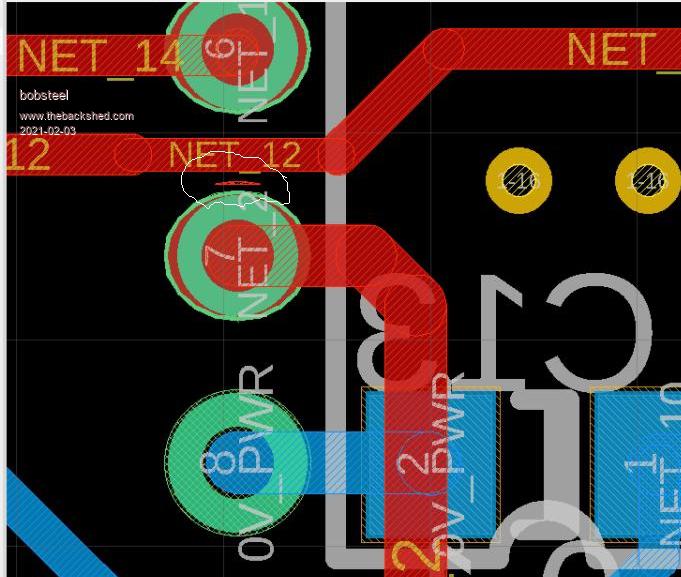 |
||||
| Solar Mike Guru Joined: 08/02/2015 Location: New ZealandPosts: 1204 |
There is only 1 one sheet in the schematic, should look like image few posts back; perhaps the export process doesnt exactly match your software. Clearance is fine, no errors at this end; have finished pcb here, no issues looking at it. Cheers Mike |
||||
| The Back Shed's forum code is written, and hosted, in Australia. | © JAQ Software 2026 |
