
|
|
Forum Index : Solar : Picaxe 20X2 60 Amp Mppt Charge Controller
| Author | Message | ||||
| Solar Mike Guru Joined: 08/02/2015 Location: New ZealandPosts: 1204 |
While waiting for the last 14M2 charge controller pcbs to come back, decided to do an upgrade to the design using the 20X2 chip, gathering the best features from previous designs to hopefully make a better controller. Using the 20X2 allows for 64 Khz pwm and extra capability; the higher pwm frequency will keep the inductor size down running at the higher charge currents. For this higher power 60 amp design I have standardized the input\output cap's to the smaller 18mm dia foot print and more of them, each has a >3 amp ripple rating, this allows for better heat dissipation over the bulky 35mm types. The driver pcb is the same design as for the last 14M2 version and allows optionally a synchronous buck converter. Have expanded the removeable led display section to include a relay that is activated when in float charge mode and a 20 amp high side mosfet switch that is under cpu control, the load can be turned off on at low\high abnormal battery voltages. I have a number of common modules such as filters and 1-Wire comms. and have used them here to save pcb space and make it easier to build. The mosfets are mounted under the pcb as previous, but clamped to the heatsink by the pcb itself. For this prototype using 1oz copper pcb traces, have allowed for soldering some thick copper wire to the main high current areas. Top: 196 x 160mm 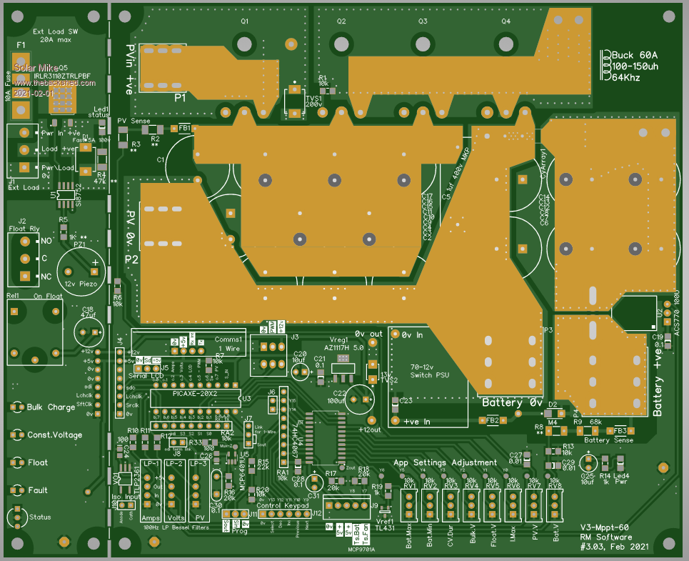 Bottom: 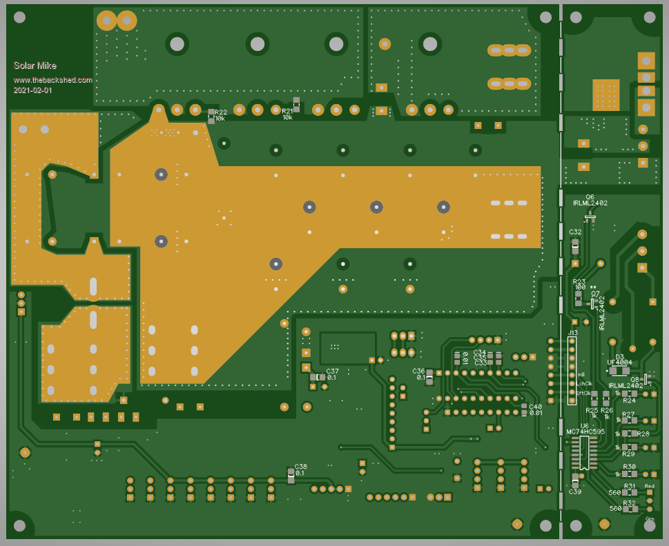 Schematics soon.. Cheers Mike |
||||
| Solar Mike Guru Joined: 08/02/2015 Location: New ZealandPosts: 1204 |
Circuit: 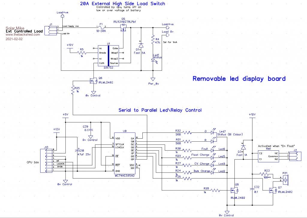 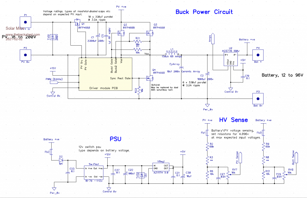 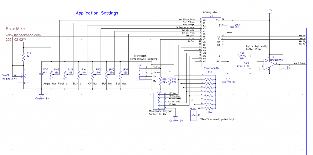 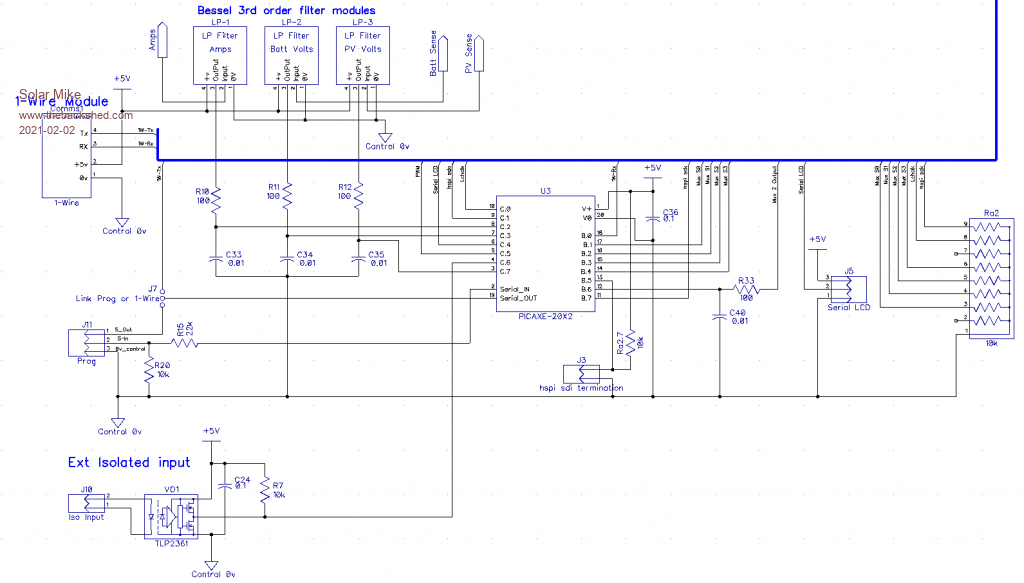 Cheers Mike |
||||
| Tomi87 Newbie Joined: 21/11/2022 Location: SlovakiaPosts: 3 |
Hello, I would like to ask you for some modifications to the MPPT Solar Charge Controller (ESP32 + WiFi), I would like to build it myself. I would need it to handle the input voltage from 4x Avancis PowerMax 155W solar panels with CIGS technology. Two in series and two in parallel would be connected. The battery would be Lifepo4 12v approx 100Ah. I would like an MPPT controller for 250V /60A control. + LEDs for charging Bulk, Absorption, Float. What modifications would you recommend in terms of replacing parts, especially MOSFETs and other parts if needed. It would be better to show the changes in the schema. I am also sending the datasheet of the solar panel + parameters Voc, Isc, etc. 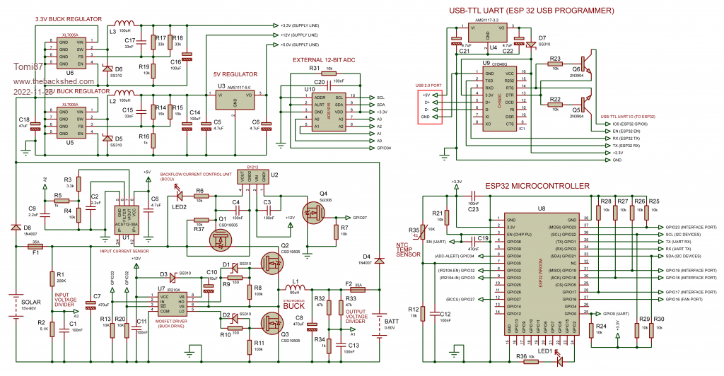 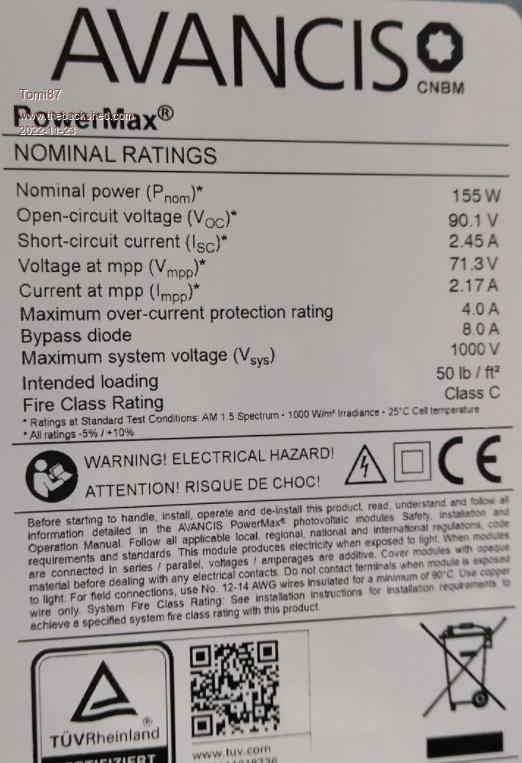 FE_PD_PowerMax_Datasheet_EN_V4.6.z_2020_09_web.pdf Edited 2022-11-23 20:47 by Tomi87 |
||||
| Solar Mike Guru Joined: 08/02/2015 Location: New ZealandPosts: 1204 |
Its good that others are interested in having a go designing a mppt charger. I have a few general observations about that design for use at higher voltages. 1: Those panels are a high voltage 90voc, with 2 in series giving 180v. This presents a few issues when charging a 12V battery. The pwm buck duty cycle will be very small, so the mosfets will have high peak currents leading to inefficient operation. High voltage mosfets have quite high on resistance compared to the lower voltage types, thus necessitating multiple parallel devices. I would start by placing your panels in parallel to get the PV voltage down, so you can use lower voltage mosfets 150v, for 60 amps charge current you will still require 2 devices in parallel for efficient operation. 2: Your 3.3 and 12V regulators wont run off higher input voltages, I would power them from a 12V buck\boost switch supply running off the 12V battery AND replace the low 3.3v switching supply with an analog regulator. This will get the EMI noise down especially for the ADC circuitry. 3: The circuit has no means to measure the battery charge current, there is no need to measure the input PV current, after all it is max battery charge amps that is required when in MPPT phase; also to prevent the synchronous buck stage from acting as a reverse boost converter during very low buck duty cycles its important to know when the battery current could start reversing, when this condition starts and detected by the very low charge or reverse current then the synchronous rectifier mosfet can be disabled so preventing this disastrous condition. You will require a different mosfet driver to achieve this. 4: Power the buck driver from a 1212-1W isolated psu block rather than using the D3 bootstrap diode, with batteries the charge currents may be halted, thus your driver chip will have no volts available. 5: PV and Battery voltage sensing; I have found simple 3rd order active filters work much better than using just a large capacitor alone, the response is quicker and noise level lower. I now use an analog mux for selection of all analog signals with the mux output going via a single 3rd order filter then the CPU ADC. Cheers Mike |
||||
| Tomi87 Newbie Joined: 21/11/2022 Location: SlovakiaPosts: 3 |
Could you please redraw the MPPT controller schematic for me? because I don't know much about electronics... at least 150V/45 amp (60 amp), I will put the solar panels in parallel... for now I would have a 12V lifepo4 battery and after some time I will buy another 12V battery. The Victron Energy 150/60-Tr MPPT is very expensive. ..I will be very grateful to you for that...I also want to build something original...I will be happy if you then send me the scheme to my email: tomas.matokar@post.sk... or .... matokar . tomas@gmail.com Edited 2022-11-25 04:00 by Tomi87 |
||||
| Solar Mike Guru Joined: 08/02/2015 Location: New ZealandPosts: 1204 |
Sorry I am not in a position to re-draw someone else's schematic, you would have to ask Āwhomever designed it to add the modifications you require and redesign the circuit boards to suit. There are many free cad packages around, I could suggest you get one and try drawing it up yourself. Cheers Mike Edited 2022-11-25 12:44 by Solar Mike |
||||
| Tomi87 Newbie Joined: 21/11/2022 Location: SlovakiaPosts: 3 |
and could you provide me some of your mppt projects? I only want it on ESP32. |
||||
| The Back Shed's forum code is written, and hosted, in Australia. | © JAQ Software 2026 |
