
|
|
Forum Index : Solar : PV Over Voltage Limiter
| Page 1 of 3 |
|||||
| Author | Message | ||||
| Solar Mike Guru Joined: 08/02/2015 Location: New ZealandPosts: 1204 |
During testing of these controller designs on a common set of panels, these series strings can reach quite high voltages when unloaded, for instance I want to put up a 5s array where each panels unloaded voltage is 40v, but the mppt voltage is a lot lower 31.5V; this gives a working point of 155V which is ok, the controller can handle that. However during float or first connection the PV input voltage is around 200V, dangerously close to the input capacitor max ratings and the mosfets max voltage. Rather than use higher voltage caps and higher spec'd mosfets (with higher on R) thought it may be simpler to place a device across the PV input that allowed a load be placed across the array when the voltage increased beyond a set value. A voltage sensitive shunt load springs to mind, using an IGBT device running in linear mode, so the higher the voltage above a set point, the more it turns on, thus lowering the voltage. Couldn't find anything suitable on the net, so here's the result of a thought experiment. IGBT devices are quite robust, their SOA curves have good operational area down to DC and they are cheap. The old style LM324 op amp can run single supply at quite high voltages, certainly high enough to drive the IGBT in its linear region. The PV voltage is compared to a 2.495 reference by a subtractor circuit, the difference multiplied by the gain of approx 100 is the linear drive. 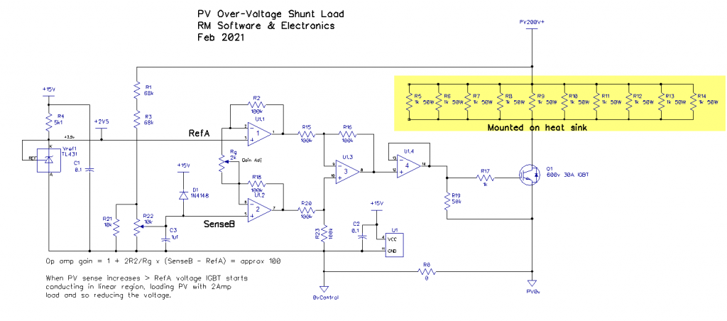 I could use a bunch of 50W resistors or something like an old single bar heater as the load. Has anyone ever built something like this... Cheers Mike |
||||
| Warpspeed Guru Joined: 09/08/2007 Location: AustraliaPosts: 4406 |
It probably will not need much load to pull it down to a safe maximum, the panels are not very efficient up there... Also beware of cloud edge effect, it can add quite a lot more open circuit voltage to what you expect to see in a clear blue sky. Cheers, ĀTony. |
||||
| wiseguy Guru Joined: 21/06/2018 Location: AustraliaPosts: 1286 |
Good idea, a shunt "dump" has merit for limiting the peak voltage to <150V, I once did a similar dummy load, but I used the Silicon devices themselves as an active load. If you parallel say 4 x STGW30H60D devices (~$4ea) they can handle a max Tj of 175 deg and for 4 a combined >1KW maximum dissipation. In this app 0.5A ea at 200V its 100W per device for ~ $16 and save ~ $40+ worth of resistors. They are supposedly excellent for sharing when paralleled but I would be tempted to use a shunt resistors on each emitter (0.1 - 0.5 Ohm)and 1/4 of a quad opamp for each device , to guarantee equal sharing and control them with a similar front end to your schematic. You could also start a small Dc/Dc when >150V for example and start a cooling fan on the heatsink. Edited 2021-02-17 00:30 by wiseguy If at first you dont succeed, I suggest you avoid sky diving.... Cheers Mike |
||||
| InPhase Senior Member Joined: 15/12/2020 Location: United StatesPosts: 178 |
Is there any useful work that could be done when the panel voltage is that high? Run a pump, heat some water? |
||||
| noneyabussiness Guru Joined: 31/07/2017 Location: AustraliaPosts: 527 |
Be careful though, a mosfet or IGBT in linear region will not handle the same power loading as when its " on " .. they develop " hot spots " on the die etc. which can cause premature failure at no where near there ratings... IGBT info There is a bit of info, particularly section " 2.4.4 " ... Poida experienced this earlier as he kept killing hy4008s at very little loading in linear region on his test load... I think it works !! |
||||
| wiseguy Guru Joined: 21/06/2018 Location: AustraliaPosts: 1286 |
Thanks for your comments Noneya - I have to admit that I have very limited experience with IGBTs especially in the linear region. I assumed (wrongly?) that using the STGW30H60D which is a 60A device & that using it at 120th of its rating would probably be ok and it looked well within the SOA but that does not indicate true static data. So until I have done some further experiments to back it up (or not) I withdraw the suggestion of using IGBTs in their linear region. Resistors may well be the right answer. If at first you dont succeed, I suggest you avoid sky diving.... Cheers Mike |
||||
Revlac Guru Joined: 31/12/2016 Location: AustraliaPosts: 1257 |
I haven't put much thought into this yet, but I have seen this over voltage when panels are unloaded, it can get quite close to the voltage limits of some controllers. One thought, whats wrong with using some sort of motor speed controller driving a dump load? It could be made variable to compensate for the amount of over voltage and the amount of load required couldn't it? Or something like it. Cheers Aaron Off The Grid |
||||
| Warpspeed Guru Joined: 09/08/2007 Location: AustraliaPosts: 4406 |
If you look up the safe operating area, there is NO dc safe operating line, which indicates the device is basically highly unstable in the linear condition. The longest period it is rated to hold a single pulse of current is 1ms, and that might be something like 5 amps at 150v for one millisecond. So its pretty useless in the linear region for any application. Mosfets are much better, but still have their limits. A good "big mutha mosfet" for higher voltages might be an FDA50N50. There are better ones, but not at the price of the FDA50N50. Its an absoluterly huge hunk of silicon with a power rating of 625 watts at 25 Celsius junction temperature. https://www.onsemi.com/pub/Collateral/FDH50N50-D.PDF Dc safe operating area about three amps at two hundred volts. That does not sound like a lot, until you realise that is 600 watts !! It would do it too, but it would require a refrigerated heatsink to keep the junction at 25 Celsius. That is not realistic, the device will need to be derated for use with any practical heatsink. But its stable, no hot spots or thermal runaway. But you still need to derate it according the the thermal resistance of the heatsink, and that three amp safe area rating must be reduced at least half, if its not going to burn up on even a very large heatsink. So really linear operation of anything is just not practical at higher voltages. Best to hard switch one or more big resistors such as heating elements. Edited 2021-02-17 10:23 by Warpspeed Cheers, ĀTony. |
||||
| Solar Mike Guru Joined: 08/02/2015 Location: New ZealandPosts: 1204 |
Excellent, thanks for the comments, looks like the linear mode is not going to work with IGBT's; even that "Big mutha Mosfet" which has a DC load line on the SOA graph is going to be touch and go with only a few amps, at these high voltages anyway. Will have to think of some other way, that switches in multiple loads as required to keep the PV voltage from increasing too high, preferably not having a cpu in the mix. Cheers Mike |
||||
| Warpspeed Guru Joined: 09/08/2007 Location: AustraliaPosts: 4406 |
Its going to be difficult to stop it cycling if one big load is simply switched in and out. It might require say three binary weighted loads that can switch in sequentially. That will probably still cycle the least significant bit, but that will be far less dramatic, and probably will not matter. One other idea just occurred to me. How about one of those LM3914 bargraph chips ? They illuminate a ten led bar graph, and the input voltage can be offset so the start and end leds can have independently set voltage levels. Edited 2021-02-17 13:57 by Warpspeed Cheers, ĀTony. |
||||
| Solar Mike Guru Joined: 08/02/2015 Location: New ZealandPosts: 1204 |
Was just looking at those, they are designed to pull low with constant current in each led, means I would have to invert each output as the voltage increased to turn the mosfets on in sequence. I imagine max of 8 switched loads would be ok, it doesnt have to be that accurate. Edit: Easy to do with a 14pin CPU ! Mike Edited 2021-02-17 15:01 by Solar Mike |
||||
| Warpspeed Guru Joined: 09/08/2007 Location: AustraliaPosts: 4406 |
Yes indeed !!! Cheers, ĀTony. |
||||
| Solar Mike Guru Joined: 08/02/2015 Location: New ZealandPosts: 1204 |
Use something like this, 8 comparators each connected to an IGBT\Load, connected in place of the IGBT in the original circuit. 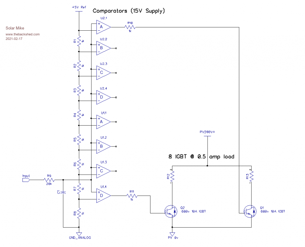 Mike |
||||
| Warpspeed Guru Joined: 09/08/2007 Location: AustraliaPosts: 4406 |
Yup. That is basically what is inside an LM3914, but with a pair of discrete quad op amps, and a few 1k resistor packs, it should be able to work a whole lot better. A bit of transient protection across the IGBTs might be a good idea. Edited 2021-02-18 10:40 by Warpspeed Cheers, ĀTony. |
||||
| wiseguy Guru Joined: 21/06/2018 Location: AustraliaPosts: 1286 |
Solar Mikes topic initially caught my attention as I have been playing with active loads lately. I needed to sink 220A at 2.8V for a high power single cell charger calibration. We have 2 x 200A programmable loads of the ElektroAutomatik variety that refused to work in this application. Sometimes the 2 control loops of the power supply and of the load can interact if there is a clash of phase shift and Gain margins and they can oscillate etc. So I was considering making my own load to have more control, what to use ?? Resistor (0.012ohms at 225A hmmm) BJT, BJT Darlington, Mosfet ? IGBT (NO!!) Most transistors suitable for the task with saturation voltages below 1.5V at >10A are expensive TO3s. It appears that to dissipate 1kW at 250A currents is going to cost upwards of $100-$200 just for the transistors! Whilst investigating Mosfets I found some devices of interest from IXYS designed for linear applications. Their on resistance is too high to be considered for this application but they appear ideally suited for Solar Mikes active load. They are 500V and 1KV rated devices with current abilities of 24A. They have a generous SOA but of course subject to case temperature control (good heatsinks and fan). Article Article_Linear_Power_MOSFETs.pdf Data sheet Linear_IXTH24N50L_Datasheet.PDF Without trying to Hijack Solar Mikes thread too much has anyone created a decent variable dummy load that can operate down to 1,5V @ say 250W ? I need ~1kW so could scale accordingly. If at first you dont succeed, I suggest you avoid sky diving.... Cheers Mike |
||||
| Warpspeed Guru Joined: 09/08/2007 Location: AustraliaPosts: 4406 |
Mike, you can buy cast iron grid resistors that have those kinds of ratings. These are usually strung in series to make up very high power resistor banks. They do in fact offer a single 0.012 ohm 200 amp resistor ! But it would probably be better to connect several higher values in parallel to spread out the heat and provide a much greater stability of resistance. https://www.widap.com/wp-content/uploads/artikel_doc150_31.pdf If you need to have precise electronic regulation, arrange a fixed resistor to carry the bulk of the current, then you may only need to control a small fraction electronically. Cheers, ĀTony. |
||||
| wiseguy Guru Joined: 21/06/2018 Location: AustraliaPosts: 1286 |
Hi Tony, I cant find a distributor in Australia and I am guessing it would be >$200. I do like the resistors though - would be good in winter lol The resistor idea I designed something quite similar years ago (never built) and promptly forgot about it. It was basically as you suggest a variable load 10A and a number of resistors that are automatically selected according to the load you dial in. It had monitoring for total current so could trim the active load component to keep the total current a constant. Maybe I should still go that way, I have some huge area heatsinks that need a use... Edited 2021-02-18 19:53 by wiseguy If at first you dont succeed, I suggest you avoid sky diving.... Cheers Mike |
||||
| nickskethisniks Guru Joined: 17/10/2017 Location: BelgiumPosts: 474 |
If you want to keep it simple and cheap I would experiment with cheap "Single DIE" mosfets. Each mosfet will need its own opamp and sensing resistor to regulate the mosfet in lineair region. I made a li-ion battery load/tester with an IRF630 or IRF640, forgot it, it was capable to do 5A quite easily. It could be hard to draw 5A at 1,5V because it has a high Rdson. I was convinced the IRF630 was a single die mosfet, but I can't find proof of it... You will need a lot but it wil help spreading the heat if you place them evenly across the heatsink. You can even make pcb's or it that would make it verry nice. You don't want to run mosfets hot in their lineair region, they die fast... And that' difficult with high power lineair mosfets. Trying to test LTO batteries? Another option you can investigate is using a few inverter boards hooked up as buck regulator. Or even more appropiate, your mppt controller board. Then hook up a low value resistor, the batteries as input. With controlling the dutycyle you can regulate the input current. You will have a (smallish?) ripple current, depending on your inductor. My mppt controller (the one in poida's mppt project) can do 100A easily when active cooled and high enough duty cycle. Edited 2021-02-19 01:01 by nickskethisniks |
||||
| Warpspeed Guru Joined: 09/08/2007 Location: AustraliaPosts: 4406 |
Cast iron is one of the cheapest metals around. Those large resistor banks literally use hundreds of the things, bought individually they may not as expensive as you might think. Cheers, ĀTony. |
||||
| Solar Mike Guru Joined: 08/02/2015 Location: New ZealandPosts: 1204 |
I did look at those linear mosfets, RS has them > $50 each, at 200v they are still only good for a couple of amps; so that rules them out for me, as too expensive. There are plenty of designs around for high current variable loads using the generic 2N3055, I remember 30 years ago one of the techs at work built one (Electronics Australia Mag) that had about 10 of them on a 400mm long heatsink; we used to use it for testing power supplies up to 30 odd amps. Think I will go with Warps idea of multiple mosfets switched hard on each with a 100W resistive load (Nichrome wire? from an old heater) Cheers Mike |
||||
| Page 1 of 3 |
|||||
| The Back Shed's forum code is written, and hosted, in Australia. | © JAQ Software 2026 |
