Notice. New forum software under development. It's going to miss a few functions and look a bit ugly for a while, but I'm working on it full time now as the old forum was too unstable. Couple days, all good. If you notice any issues, please contact me.
Solar Mike Guru Joined: 08/02/2015 Location: New ZealandPosts: 1218
Posted: 11:57am 10 Apr 2021
Copy link to clipboard
Print this post
This project originally started as a PV voltage limiter, to limit the max PV voltage supplying a charge controller as it unloaded the PV array; primarily to allow me to test out a variety of differing designs using the same high voltage panels. This idea works fine on the smaller array, but I'm installing a >6KW 200v array and there would have been considerable heat and big resister banks.
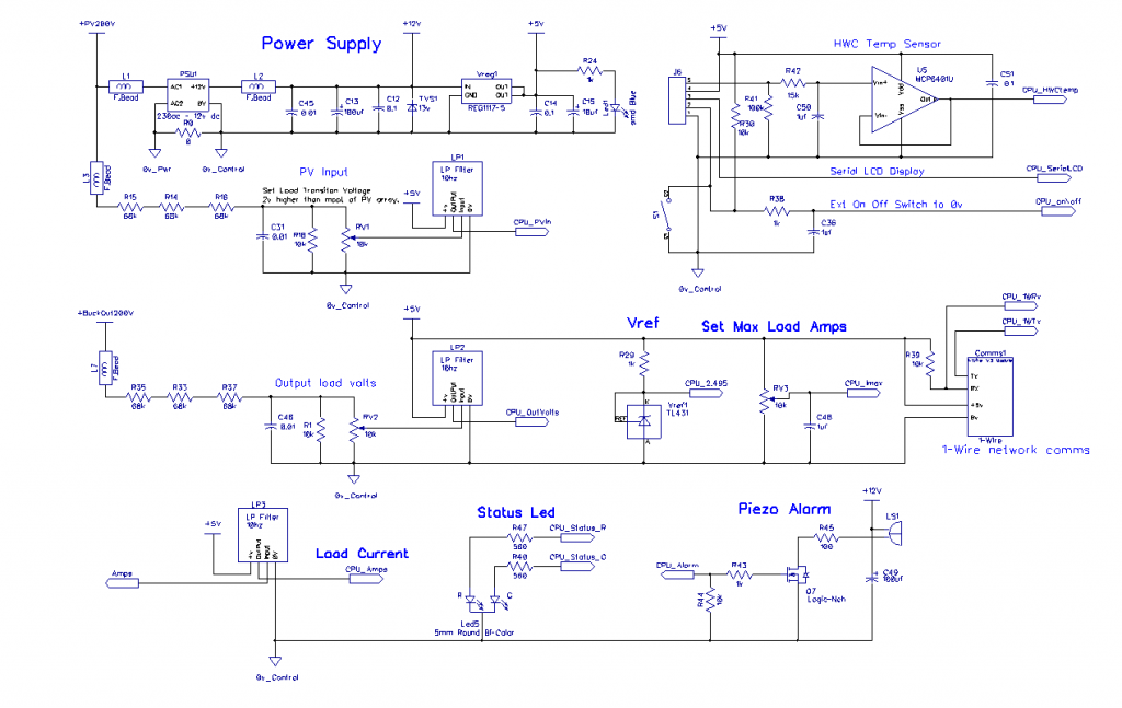
So with all this potential extra power going to waste when the 100V bank is charged, I want to incrementally divert the load off the battery PV controller(s) as they near completion and send it to one or more hot water resistive elements, these are mounted in a large 1000L tank built from timber and lined with rubber sheeting as used on roofs; this warmed water will be used in a plant propagation house. It could also be connected to a standard HWC via the normal thermostat and I will do this for my testing with a small 90L cylinder I have sitting in the shed. For lower than 230v supply I will use a 6 or 8KW element or couple in parallel.
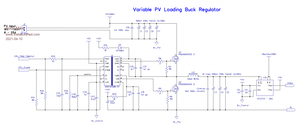
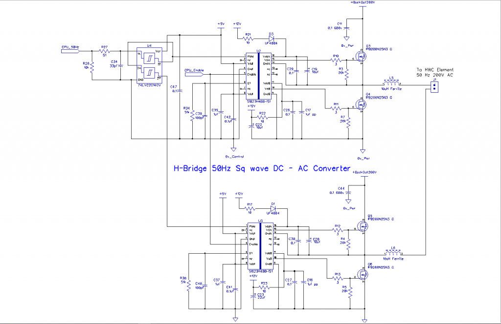
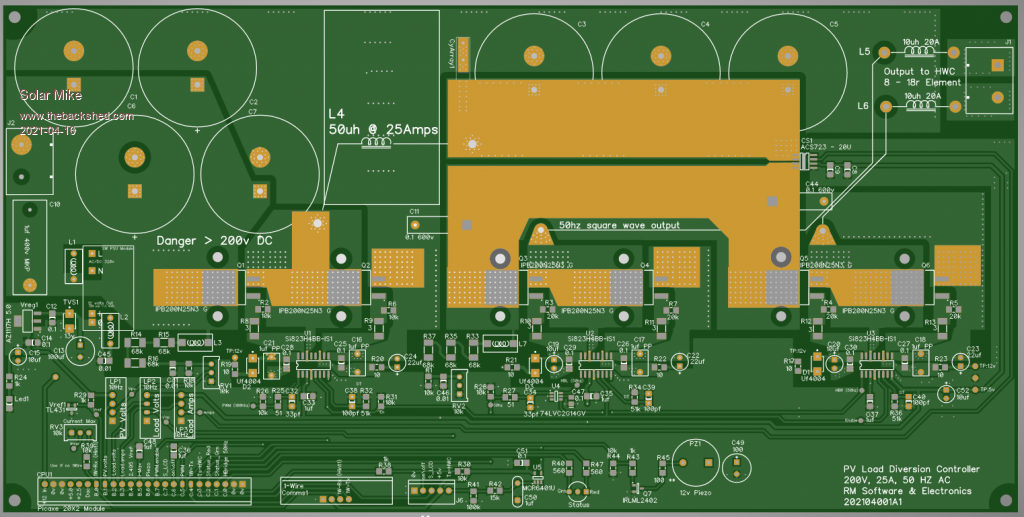
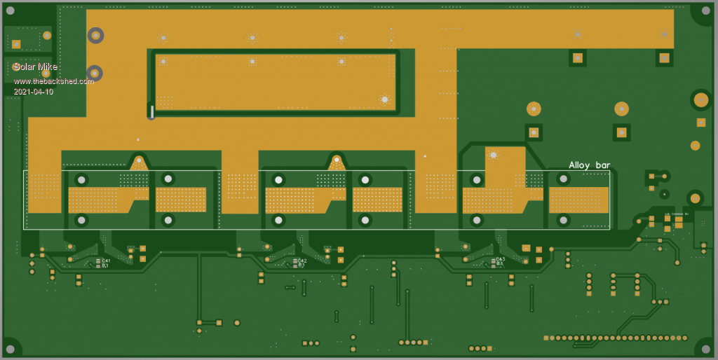
In order for this scheme to work the diverter should start loading up the PV array just above the expected MPPT voltage, as the array volts go above the MPPT point when the charge controllers start unloading the battery as it nears fully charged. I have elected to use a simple buck converter to place a variable controlled load on the array, the buck output powers an H-Bridge arrangement to convert the variable DC power to square wave AC at 50hz, thus allowing the standard thermostat and over temperature protection to work as normal. I have used surface mount DPak 250v 88A mosfets, with the bottom of the pcb insulated and clamped to an alloy bar 25mm wide bolted to the case, with up to max loading of 20 amps or so they are only dissipating a few watts each. PWM to the buck converter is 100Khz, and 50% duty 50hz to the H-Bridge.
High DC voltages are dangerous, all my DIY controllers have a common 0v rail for battery and PV, this makes things a bit easier (safer) to manage as none of it is floating. If anyone wants to build this, the final gerbers will be posted here as some point, but you must ascertain your charge controller has the same common 0v rail that never gets disconnected.
Schema:
PCB 300 x 150mm:
Cheers Mike
Davo99 Guru Joined: 03/06/2019 Location: AustraliaPosts: 1585
Posted: 03:25am 11 Apr 2021
Copy link to clipboard
Print this post
Never cease to be amazed how you can just sit down and design this stuff like it's painting a fence or something.
The diversion idea for heating water is brilliant too. Plants love warm temperatures that's for sure!
Solar Mike Guru Joined: 08/02/2015 Location: New ZealandPosts: 1218
Posted: 10:36am 11 Apr 2021
Copy link to clipboard
Print this post
Blame it all on that crystal set I built as a kid over 50 years ago.
Solar Mike Guru Joined: 08/02/2015 Location: New ZealandPosts: 1218
Posted: 05:48am 12 Apr 2021
Copy link to clipboard
Print this post
Gerbers sent off today, I had better get cracking and put up the PV array on top of the 12M container.