| Author |
Message |
brucedownunder2
Guru

Joined: 14/09/2005
Location: AustraliaPosts: 1548 |
| Posted: 11:59pm 16 Apr 2021 |
 Copy link to clipboard Copy link to clipboard |
 Print this post |
|
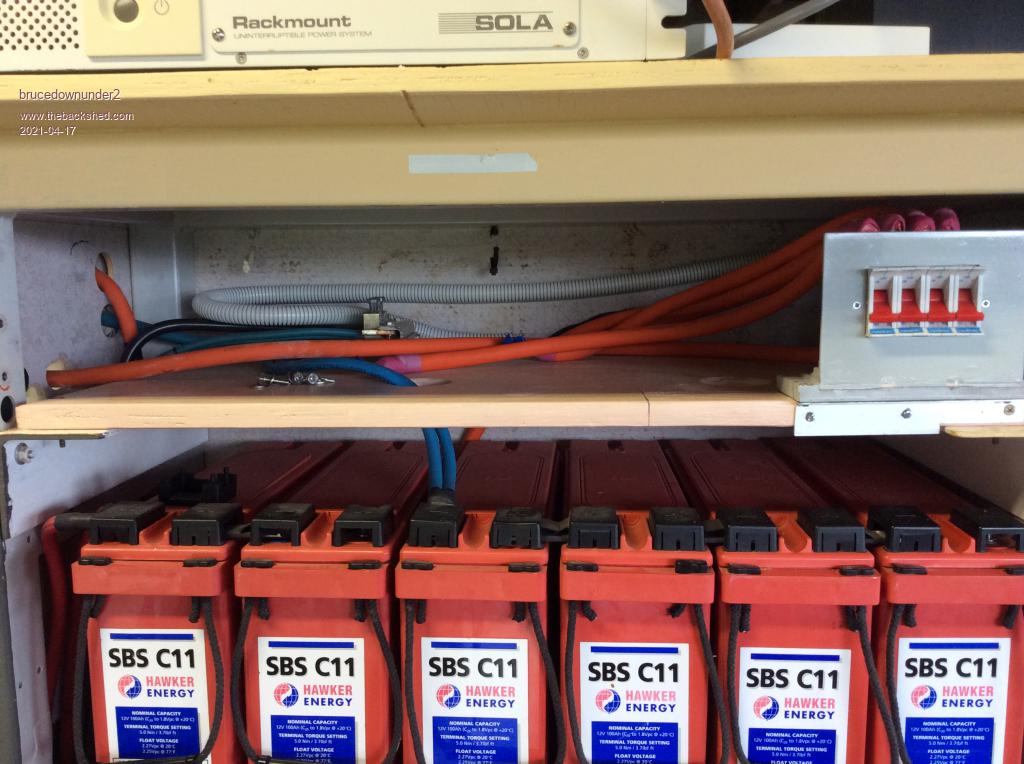
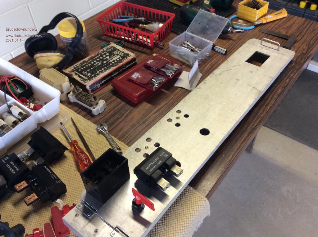
I'm building a new panel for switching three battery banks ,individually or ganged.
The switches are those cheap battery switches on e bay ,OK if you always remember to lighten the load if they are "ON" and you decide to turn them "OFF"., although I've not "welded" any contacts up in 20 years, so I must be doing something right.?
I use the 100 Amp domestic house entry fuse holders and the cartridge type fuses-have blown one of those ,was late in the afternoon and I was tired, you learn fairly quickly after the event !!. nothing damaged.
The battery cables are 50mm ,so what I do is divide the conductors,heatshrink them into two bundles and they go nicely into the connection brass block, there being two entry ports. Also makes the cable ,if you make the tails ,say 20mm long , fairly flexible for when I open and close the panel , as it's mounted on hinges for me to open and get behind it for all the cables.
OK, I hope you have a nice weekend,
Bruce
Bushboy |
| |
Jacob89
Newbie

Joined: 10/09/2017
Location: AustraliaPosts: 40 |
| Posted: 01:59am 17 Apr 2021 |
Copy link to clipboard |
Print this post |
|
I like those domestic 100 amp fuse holders. I use them on my charge controllers. The holders and the fuses are very cheap, and I haven't been able to find any reason they shouldn't work on low voltage DC. |
| |
brucedownunder2
Guru
Joined: 14/09/2005
Location: AustraliaPosts: 1548 |
| Posted: 02:05am 17 Apr 2021 |
Copy link to clipboard |
Print this post |
|
Yes,
and just a handy point , you can get ones that are rear entry for the cable or side entry at the ends.
Bruce
Bushboy |
| |
Revlac

Guru
Joined: 31/12/2016
Location: AustraliaPosts: 1257 |
| Posted: 09:36am 21 Apr 2021 |
Copy link to clipboard |
Print this post |
|
Thought I would Put the question here, maybe others have tried this before.
The idea is to be able to switch 2 separate banks, 2 or 3 separate controllers ,one on each battery bank, and then switch to either bank or both without the need to turn off the solar input to the controllers?
The scenario, we might have a lot of demand on one battery set and need some more solar power fed in.
One idea is to use A resistor wired between the first battery and the controller (probably need DITO as well) to keep the controller powered while switching to the other battery and eliminate any disruption to the controller while switching?
Two other potential problems with this, the resistor could bleed some power back to the other battery, could fix that with a blocking diode, The blocking diode might upset the controller as there is nowhere for the power to go for a short moment.
Any other better ideas?
I am aware that a Common port BMS will block all charge coming into a battery bank if a cell is over voltage or something.
Cheers Aaron
Off The Grid |
| |
Solar Mike
Guru
Joined: 08/02/2015
Location: New ZealandPosts: 1204 |
| Posted: 11:43pm 21 Apr 2021 |
Copy link to clipboard |
Print this post |
|
System I'm currently building has three 48v x 300Ahr banks each with its own dedicated PV controller. Each bank is linked to a common bus via switchable fuses, the common bus powers everything. This allows a bank to be switched out if required, but should only be switched back in, when it and the other banks are on float.
The PV controllers are not directly bus connected or commoned, but connect via isolating breakers direct to each banks terminals, ie at the lowest impedance point. There are a couple of spare controllers, but these sit in a drawer incase an active one blows up and are swapped out manually, rather by any switched system.
All banks and controllers and are active, if we add additional PV in the future it will be split into 3 sets for adding to the current controllers, or via additional controllers per set.
Cheers
Mike
Edited 2021-04-22 18:01 by Solar Mike |
| |
brucedownunder2
Guru
Joined: 14/09/2005
Location: AustraliaPosts: 1548 |
| Posted: 11:56pm 30 Apr 2021 |
Copy link to clipboard |
Print this post |
|
Thanks Mike.
I'm sort of in a similar construction stage with mine..
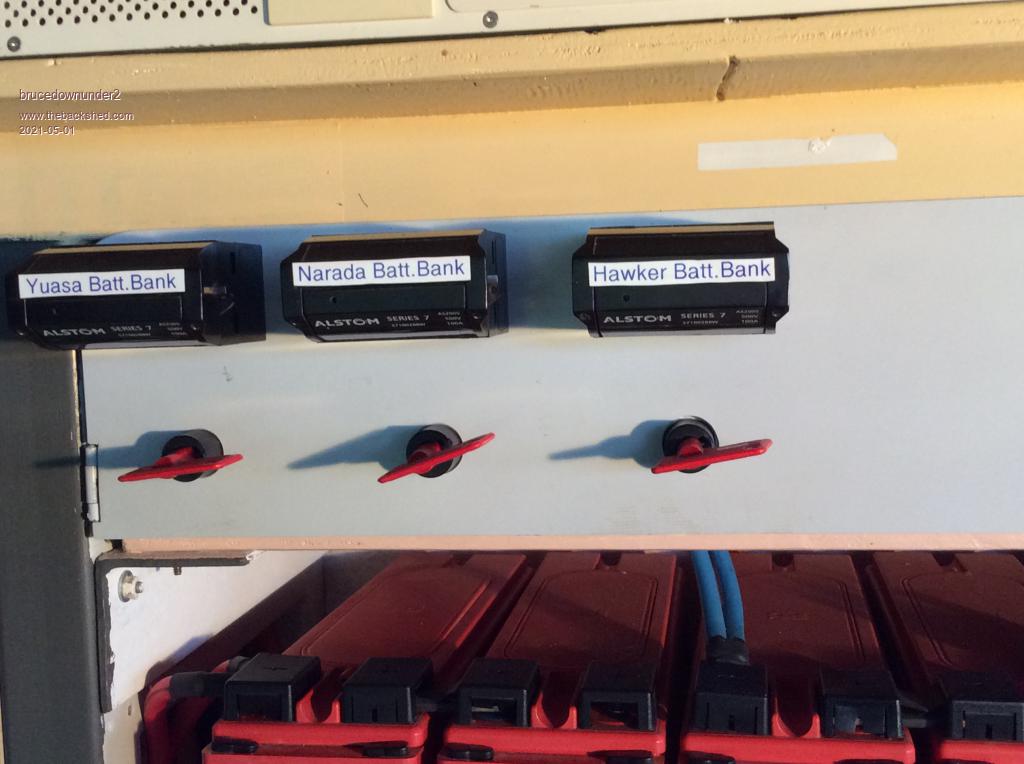
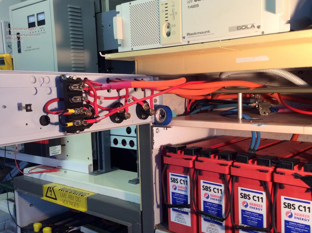
In the Photo , I have not installed the controller rotary switch ,so at present, the three master switches are on a common bar connected to my MPPT controller . The other two controllers are disconnected. I can still use any of the three battery banks .
I have drilled the position for a spare battery bank in future.
Common buss ,seperate master switches,flexability.
I'm sort of comfortable with the rotary type switches ,,,as, in my thoughts , we are mostly switching a light controller load (for it's functions).
The caution needs to be considered for the Solar output power through the controller to the batteries.
So, I will ,as I do normally, turn down the Solar power first, then switch the rotary to the next controller.
Hope you get my drift ? (I'll have three controller ,s an MPPT 60 Amp,on a dedicated array , then a CM 40Amp on 1Kw of tracker array and a CM60 amp as a back-up spare. All my equipment is 48 volt.
Bruce
Bushboy |
| |
