Notice. New forum software under development. It's going to miss a few functions and look a bit ugly for a while, but I'm working on it full time now as the old forum was too unstable. Couple days, all good. If you notice any issues, please contact me.
Forum Index : Solar : PI Pico 200V 50A Mppt PV Charge Controller
Author
Message
Solar Mike Guru Joined: 08/02/2015 Location: New ZealandPosts: 1206
Posted: 10:36am 26 Sep 2021
Copy link to clipboard
Print this post
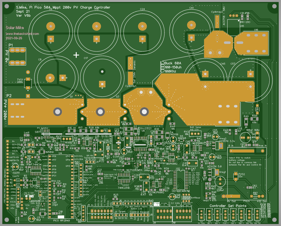
Quite like the PI Pico, its inexpensive, reasonably fast, easy to program in Python providing the 2nd CPU isn't used extensively, or even better using the upcoming Basic OS; So have decided to create a new PV controller using the Pico RP2040 module as an experiment.
Having made quite a few of these PV controllers over the years, threw this pcb together making every attempt at good practice design, no schematic for it yet, will draw that up from the pcb and check it as I go.
This design has automatic switching from synchronous\non-synchronous rectification in the buck inverter section when charge currents drop below 2 amps, thus preventing any issues at low charge rates and low duty cycles, turning the buck inverter into a reverse UP voltage converter.
Have use an analog mux to increase the number of analog inputs along with a proper 3.00 volt reference for the CPU ADC, hopefully this will allow better ADC accuracy with less noise. There will be a separate small pcb driven by serial data for mounting Led status display on the front panel.
Main power mosfets sit under the pcb and clamped to the heatsink by it, PWM frequency will be 100Khz using the Pico's PIO to implement the drive.
Have allowed for multiple controllers on the same battery bank where one is a master telling the others when to do bulk charge, go to float etc.
Here is B version 220 x 177mm:
Work on the schematic and display pcb next...
Cheers Mike
noneyabussiness Guru Joined: 31/07/2017 Location: AustraliaPosts: 527
Posted: 09:53pm 26 Sep 2021
Copy link to clipboard
Print this post
good job!!I think it works !!
Murphy's friend Guru Joined: 04/10/2019 Location: AustraliaPosts: 675
Posted: 10:16am 27 Sep 2021
Copy link to clipboard
Print this post
Mike, I'm always amazed with your PCB designs. You really put 'art' into your artworks.
Now I'm curious if you let a computer program lay out your board or is it all done in your brain. That board looks too neat for a computer layout, the tracks run all very logically and not higgedly piggedly as some computer layouts look.
Solar Mike Guru Joined: 08/02/2015 Location: New ZealandPosts: 1206
Posted: 11:11am 27 Sep 2021
Copy link to clipboard
Print this post
Hmm dunno about "art", have professionally been designing PCB's over the past 40 years, so I know many short cuts; It also helps having a professional electronics technical back ground.
Never use the auto layout features, as on the low cost software packages used here (DipTrace), the rules layout engine isn't optimal and just messes up the design, unfortunately I cannot justify purchasing Altium or similar high end software to do it.
Cheers Mike
Solar Mike Guru Joined: 08/02/2015 Location: New ZealandPosts: 1206
Posted: 11:34am 01 Oct 2021
Copy link to clipboard
Print this post
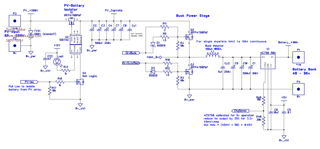
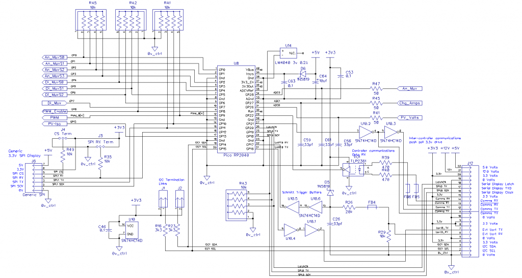
Schematic drawn up, good idea doing it, missed a couple of diodes and have swapped couple of traces around.
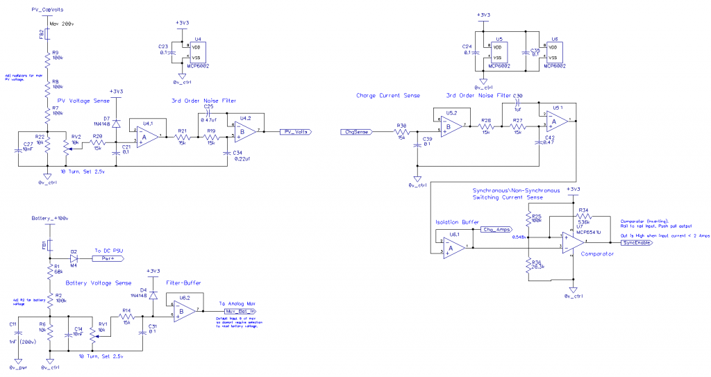
Buck Power: Nothing really special here, have used the AC758 50U current sense; it is factory optimized for 5V operation, not 3.3v, so have reduced its output by 25% so the opamps are not overloaded.
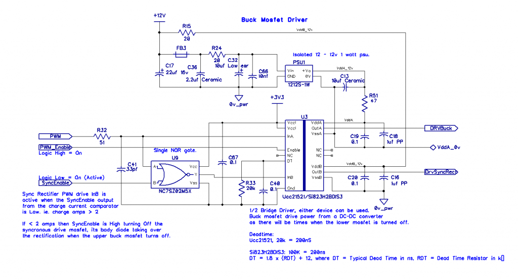
Buck Drive: Have used a dual pwm input driver, either a UCC21521 or an Si823H2BD-IS3 can be used here, both have identical pin outs. The Buck 12v power is from an isolated 1212-1W PSU, as a bootstrap config wont work here if the synchronous rectifier mosfet is turned off.
A NOR gate is used to disable the synchronous mosfet when the charge current drops below 2 amps approx.
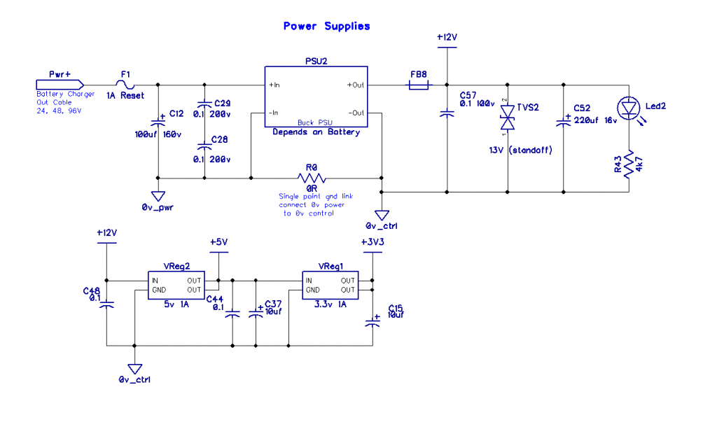
Power Supplies: 12 volt switch mode main psu followed by linear 5V and 3.3V to keep analog stage noise to a minimum.
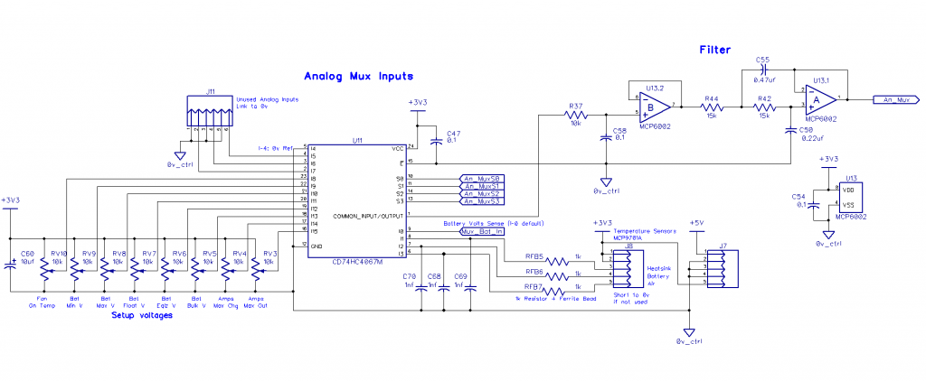
Analog Mux: As the Pico is rather limited for ADC's have used an analog multiplexer ic to expand their number. Standard 3 stage analog filter is used on the mux output to get rid of any noise.
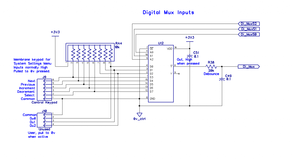
Digital Mux Inputs: Have used a MC74HC251D digital mux as a port input expander, somewhat old style, but as I have lots lying around, will use them. Want to use a simple 5 pad key board for menu selection + a couple of spare inputs.
Voltage Sensing: PV voltage and charge current go direct to the CPU ADC inputs, Battery voltage is connected to the analog mux input 0. I prefer to use analog filtering on these inputs as the noise levels with all the close proximity high current switching could be very high. A single rail\rail comparator is used to detect low charge currents and switch the buck stage from fully synchronous operation, thus preventing issues with low duty cycle operation.
CPU: Its all down to the software how well the RP2040 will work here, either uPython or Basic; have brought out some uart, I2C, SPI IO. and comms connection for linking multiple controller boards; initially I will just use a serial latched led display for showing charge status, then use one of those inexpensive LCD SPI input displays. Have added a proper 3.00 volt reference for the CPU ADC stage, using the main 3.3v switch mode noisy supply is a crap option for accuracy.
Cheers Mike Edited 2021-10-01 21:40 by Solar Mike
Solar Mike Guru Joined: 08/02/2015 Location: New ZealandPosts: 1206
Posted: 10:25am 02 Oct 2021
Copy link to clipboard
Print this post
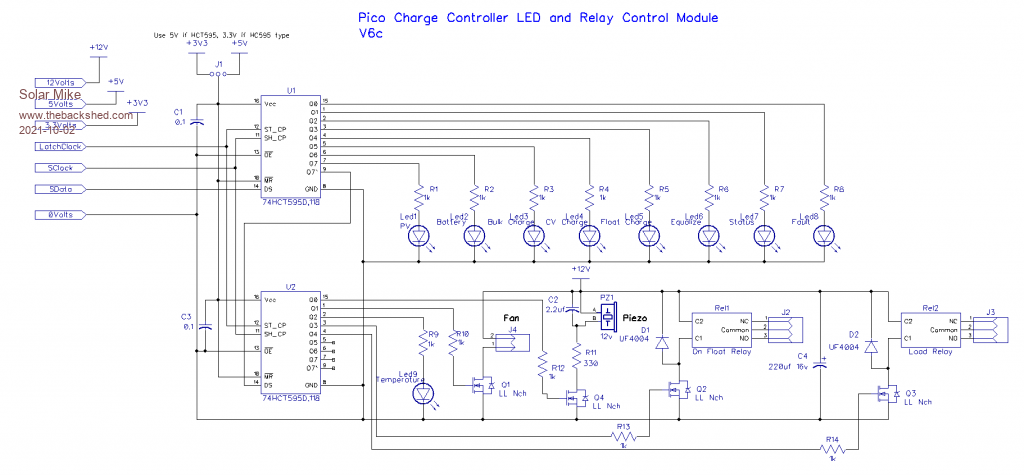
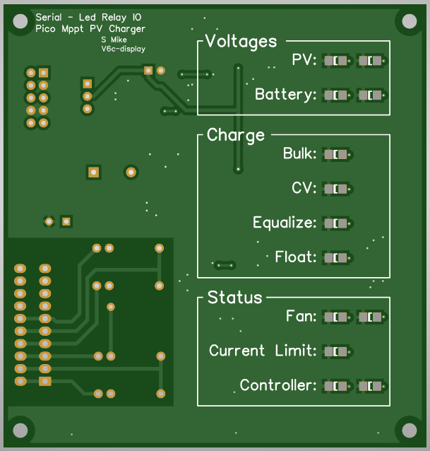
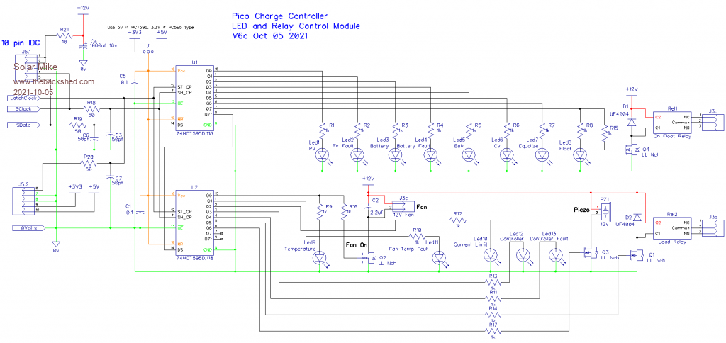
Serial latched LED and Relay module; will design a small pcb as per the schematic, that allows the leds to show through the front panel to display charge status. In the past I have made the boards black with white text and surface mount leds on the upper surface; this sits behind a slot cut in the front panel covered by clear Perspex.
Have included a couple of small control relays; "On Float", active when controller has the battery bank in a float state, this will allow external devices to place loads across the bank to make use of any excess power.
"Load", active when battery is between High\Low voltage limits; this allows control of an "On Load" contactor say supplying an inverter or other heavy load.
Cheers Mike
Solar Mike Guru Joined: 08/02/2015 Location: New ZealandPosts: 1206
Posted: 10:37am 05 Oct 2021
Copy link to clipboard
Print this post
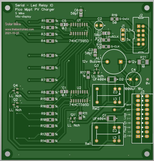
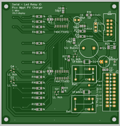
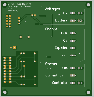
PCB done, LEDs and labels mount one one side of the board for showing through a slot in the front panel. Will get the pcb done in black with white lettering.
The circuit also altered somewhat to match layout; have included some noise filtering on the serial input and control lines to the shift registers; its a very noisy environment to work in close to high power switching.
Either HTC or HC type shift registers can be used, depending on the 3.3 or 5v selection link; note if 3.3v is used then the 4 mosfets must have suitable extra low turn on gate voltages.
PCB 86 x 90mm, shown here greater than full size:
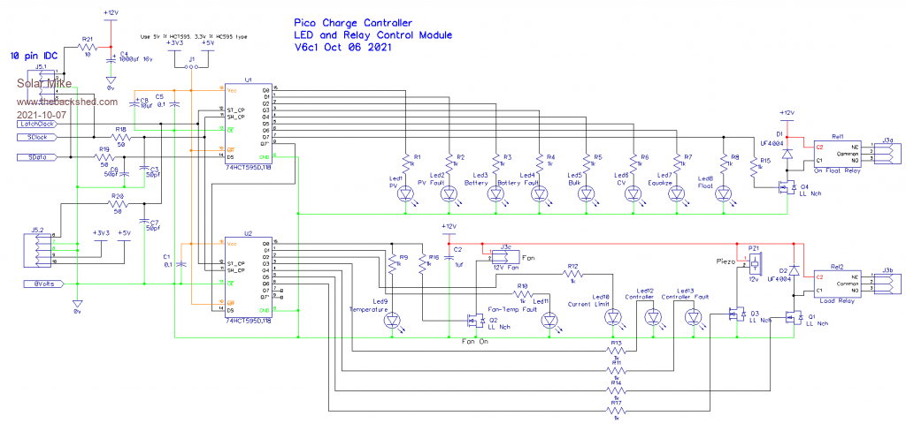
Schematic:
Have double checked everything, so will send off to be made.
Edit: Cap C2 in the schematic is missing from correct location on the pcb, will fix, 3rd time lucky.
Cheers Mike Edited 2021-10-05 20:48 by Solar Mike
Solar Mike Guru Joined: 08/02/2015 Location: New ZealandPosts: 1206
Posted: 11:04pm 06 Oct 2021
Copy link to clipboard
Print this post
OK, C2 fixed.
Cheers Mike
Solar Mike Guru Joined: 08/02/2015 Location: New ZealandPosts: 1206
Posted: 09:53am 05 Dec 2021
Copy link to clipboard
Print this post
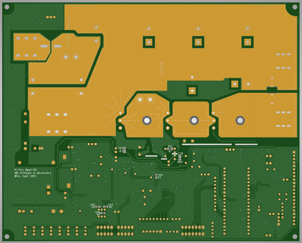
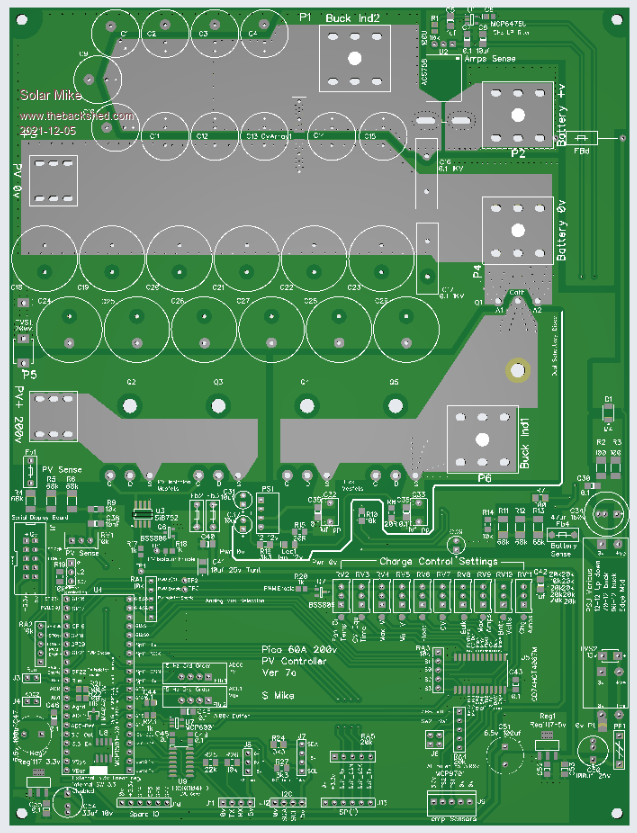
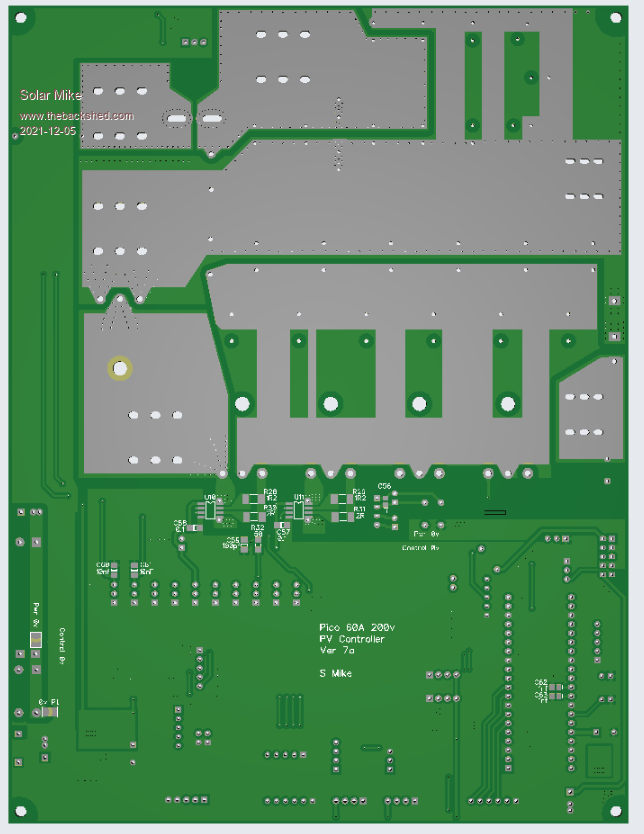
Have been phaffing around with another version of this controller when I have a spare moment; in order to make it a little more efficient by doubling up on the switching mosfets and introducing more but smaller electro's. For simplicity have gone back to non-synchronous operation and removed some superfluous controls. Uses same led IO display pcb. Firing off another board order now, so though would quickly complete the layout and include, so I can have a play over the Christmas period.
Dont have any schematic for this one so it may have an error on it, similar design to Ver6 with bits taken out, changed the power supply to the Pico, by disabling the onboard 3.3V switching psu chip and replacing with a linear 3.3V external regulator, an LM4040 precision reference is also used for the Pico ADC reference, this should completely get rid of all noise from affecting the ADC. One thing I have been very careful of is the common 0Volt signal path, there are very deliberate gaps on it to split up the higher current return paths from the low level stuff; all points terminating at a common single point.