Notice. New forum software under development. It's going to miss a few functions and look a bit ugly for a while, but I'm working on it full time now as the old forum was too unstable. Couple days, all good. If you notice any issues, please contact me.
Forum Index : Solar : Pi Pico MPPT-PWM Multi Phase PV Controller
Author
Message
Solar Mike Guru Joined: 08/02/2015 Location: New ZealandPosts: 1162
Posted: 08:36am 24 Nov 2021
Copy link to clipboard
Print this post
The previous iteration of the PWM charge controller has sort of morphed into this new design. I had wanted to re-use the existing pcb layout for the control and display section to drive a lowish power MPPT buck PV charger unit. In doing so it made sense to make the MPPT module as an add on, do the same with the PWM only and allow the main PCB control board to host either type of power unit.
Modular construction opens up more possibilities; the Pico with its high speed State Machines can be setup to output multiple synchronized phases of high speed PWM very easily. This allows me to have a design that can host 1-3 MPPT or PWM power modules whose outputs are combined in parallel with 120 degree phasing.
Advantages in doing this are many; AC current and voltage ripple in the output DC get very small; makes it easier to get high power without having to go to humungous size iron powder cores or capacitors with huge ripple current ratings, costs drop as power output increases, extend the PV array - just add another module...
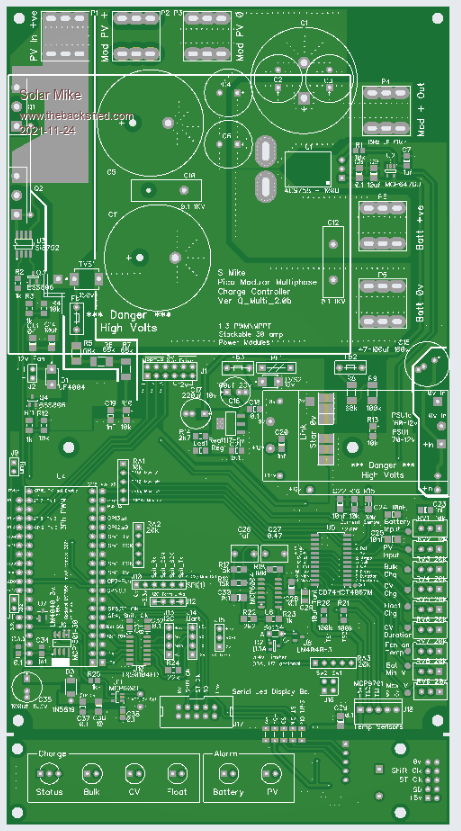
So that's what I have done, the original control board has been extended to allow up to 3 MPPT modules (97 x 80mm) stacked on vertical copper riser bars, with a drive signal to each unit. If MPPT isn't required then a lot of the bits can be left off the host controller and stacked PWM only boards substituted.
Here is the initial layout for the control host board (231 x 125mm)
Cheers Mike
Solar Mike Guru Joined: 08/02/2015 Location: New ZealandPosts: 1162
Posted: 10:29am 24 Nov 2021
Copy link to clipboard
Print this post
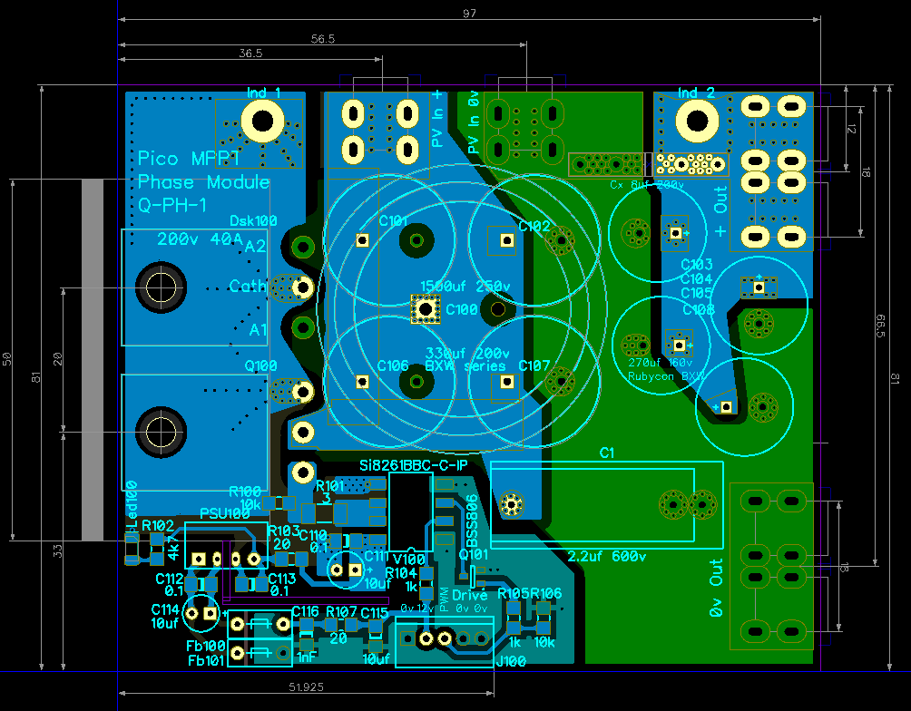
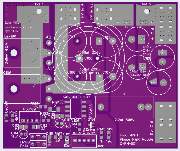
Here's the layout for the MPPT module, a single mosfet and Schottky diode are used in the buck stage, the two devices are clamped under the PCB to a 50 x 25 x 3mm alloy angle; this then bolts to the vertical heatsink or wall of the case. Small 1W 12-12v isolated PSU supplies drive power to the 4 amp Si8261BBC-C-IP isolated driver . An alternative driver is the 3 amp Fod3182 with the same pinout, but is a lot looser in its specs and not as fast, don't know if it would work at 100 Khz PWM, which I will be using for this design. PCB track spacing allows up to 200 odd volts PV input, which is what I will be using for the 100v battery bank.
Allowance has been made for differing caps, however Rubycon BXW series recommended here to get sufficient ripple rating for 30 amps output.
The buck inductor 26 turns is wound on a 50 x 25mm powdered iron toroidal core sitting off the PCB.
RT angle brass high current PCB connectors screw to the vertical copper foil conductors back to the host PCB
Will have to draw up a schematic for all of this now.
Cheers Mike
Solar Mike Guru Joined: 08/02/2015 Location: New ZealandPosts: 1162
Posted: 09:10pm 24 Nov 2021
Copy link to clipboard
Print this post
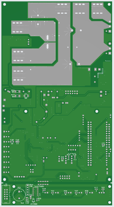
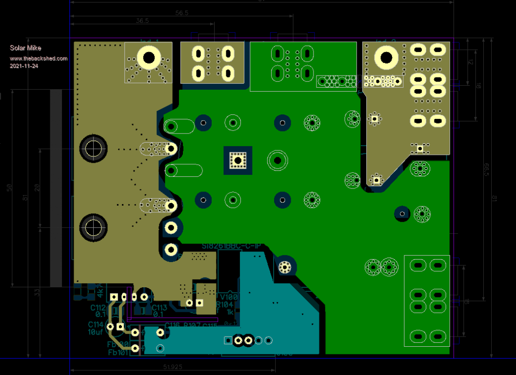
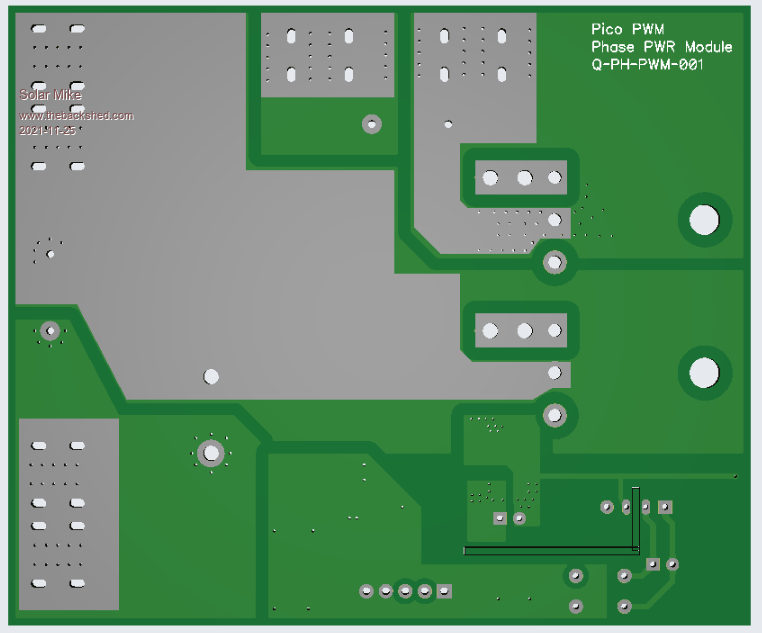
Final Gerber layout of above, 81x97mm: The white lines covering the tinned areas will be erased by the fab house process.
Mike
Solar Mike Guru Joined: 08/02/2015 Location: New ZealandPosts: 1162
Posted: 10:40am 25 Nov 2021
Copy link to clipboard
Print this post
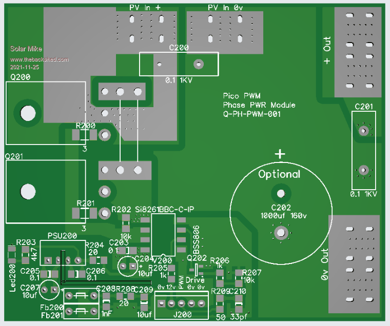
Here is the PWM only module: Uses two mosfets common source back to back, layout not nearly as critical as MPPT, as during bulk charge they are hard on 100% duty cycle, only during CV absorb phase the duty progressively gets less as the charge in the battery builds up; PWM frequency can be very low near 300 Hz.
I have a strong dislike for high current PWM chargers, they inject high ripple voltages onto the battery that exceed the manufactures common spec of 5% (lead acid), this must cause extra wear on the battery due to the micro over charging due to ripple when in the absorb and float stages.