
|
|
Forum Index : Solar : PV Load Diverter V3
| Page 1 of 2 |
|||||
| Author | Message | ||||
| Solar Mike Guru Joined: 08/02/2015 Location: New ZealandPosts: 1228 |
A new tack on seamlessly diverting power away from the PV array when it starts getting unloaded due to the battery bank getting fully charged or the battery load decreasing. In these situations the PV voltage will start rising above the mppt point, increasing to the full unloaded design voltage of the panels. Potentially there would be a lot of power available that is going no where other than extra heating of the panels themselves. As the battery load decreases I want to add additional load in a seamless fashion across the array and divert the un-utilized energy into a resistance load, whether it be a HWC element of an array of resistors clamped to the cylinder water jacket. As the PV mppt voltage is set by the panels design and doesn't change much, it seems a simple matter of having a preset trip point just above the mppt setting, when reached start applying a gradual diversion load, as the battery loading decreases then apply more load (power) to the resistor bank or element and vice versa with a feedback loop. My previous designs for this have been too complex or not enough granularity in load control; so I want something easy to setup and work with different element resistances. So why not use a buck down converter supplying the load resistance; by increasing the PWM duty from 0 to 1023, where 0 = no load and 1023 = 100% load and measuring the input PV voltage level along with a manually set trip point value using a cheap 8 pin CPU (Picaxe 08M2). The program is really simple, if the PV voltage goes above the set point then keep increasing the PWM duty cycle until equals the set point in a feedback loop. If the battery load starts increasing the the PV voltage will fall below the set point and so the diverter will just turn off. Here is first cut of the design, PCB is 100 x 100mm, the mosfet and Schottky rectifiers mount on the top layer, their few watts of heat passed to the bottom layer by the many vias, this sits on a piece of alloy + silicon insulator sheet bolted to the allow case acting as a heat sink. My unloaded PV voltages are 200V and mppt is 155V, so the devices are rated at 250V along with the 100uf 250V caps, the inductor 150uH powdered iron ring core sits on top of the caps. 10 - 15 amps output should be ok, limited by the ripple rating of the input caps, thats why I have used 10 of them for better heat dissipation rather than bigger 35mm can types. Having 4 PV arrays and controllers means I need 4 of these diverters. Will draw up the schematic next. 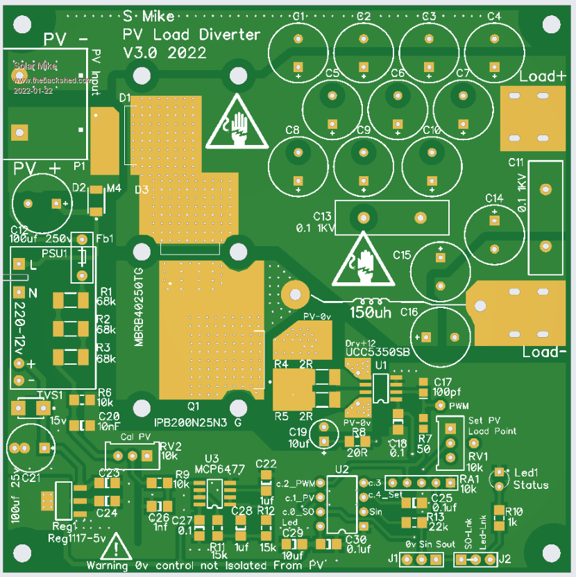 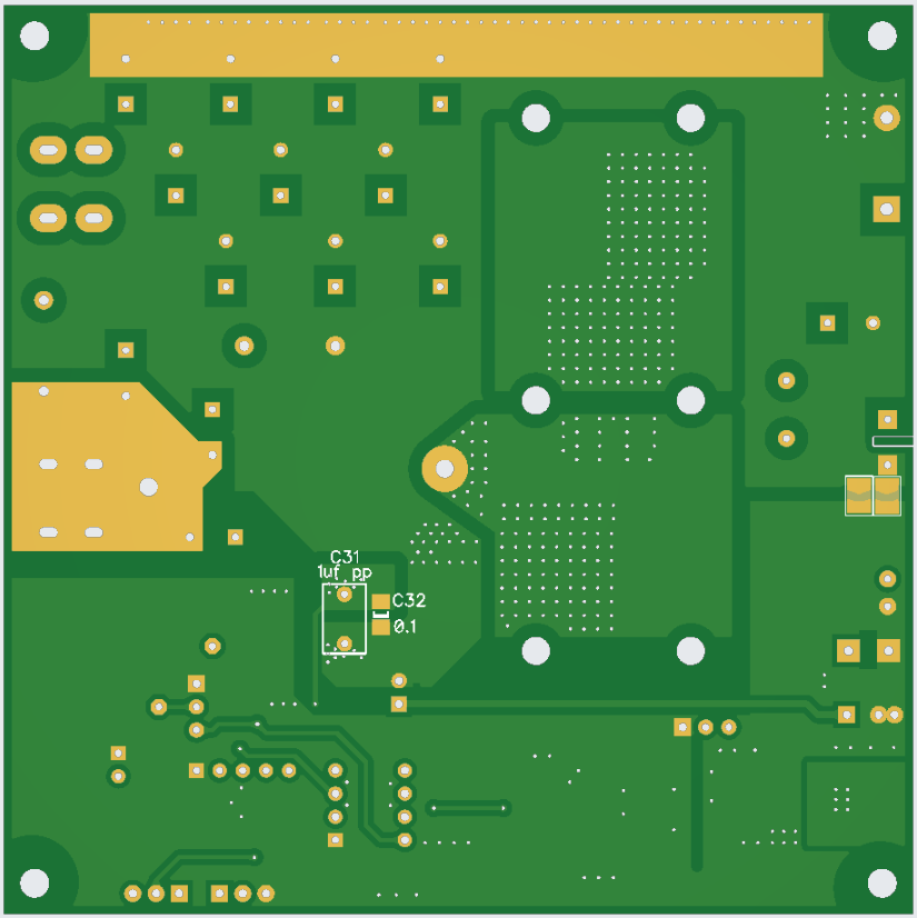 Mike |
||||
| phil99 Guru Joined: 11/02/2018 Location: AustraliaPosts: 3321 |
If the load is a hot water tank a boost converter might allow use of the original element. The thermostat might not be able to switch DC so rewire it to shutdown the PWM signal. Typical 240V element R = 15 to 20 ohms, 3kW to 3.6kW. |
||||
| Solar Mike Guru Joined: 08/02/2015 Location: New ZealandPosts: 1228 |
Remote isolated shut down is a good idea and have implemented it. Boost inverter would work better for lower voltage PV array, but requires more CPU control and bigger caps, bigger PCB and another CPU. I wont be implementing that as my array is already at 200v and a good match for the 15R elements in the non-pressurized heat exchanger coupled to the HWC. I will be using alloy cased 200w resistors bolted to a copper plate soldered to the heat exchanger, rather than water heating elements. Cheers Mike |
||||
| Solar Mike Guru Joined: 08/02/2015 Location: New ZealandPosts: 1228 |
Here is the final schematic. 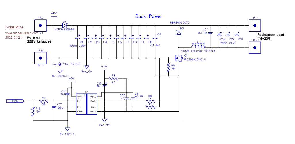 The buck converter has been implemented as LOW-side driver, using PV-ve as the 0v reference, so is linked directly to the PV making it somewhat hazardous for the unwary and requiring an isolated scope to do waveform measurements. All my controller designs are PV-ve 0v common so will be ok, some commercial controllers are not and would definitely require isolated probes. Have added an extra input rectifier in the input to prevent the 1000uf of caps back feeding a possibly large current surge into the inputs of a couple of the commercial controllers in the system, they have internal input relays and I dont want their contacts burnt off. 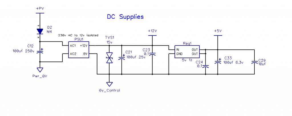 Using one of those postage stamp 220-12v switching regulators linked to the PV input to power the electronics, it has its own 100uf cap to hold up the voltage with hugely changing PV loads. 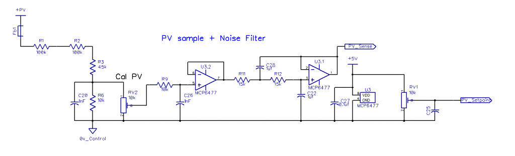 The PV input is full of switching noise, using a multi-stage active low pass filter to remove it, allows faster ADC measurements over using a single large RC combination. 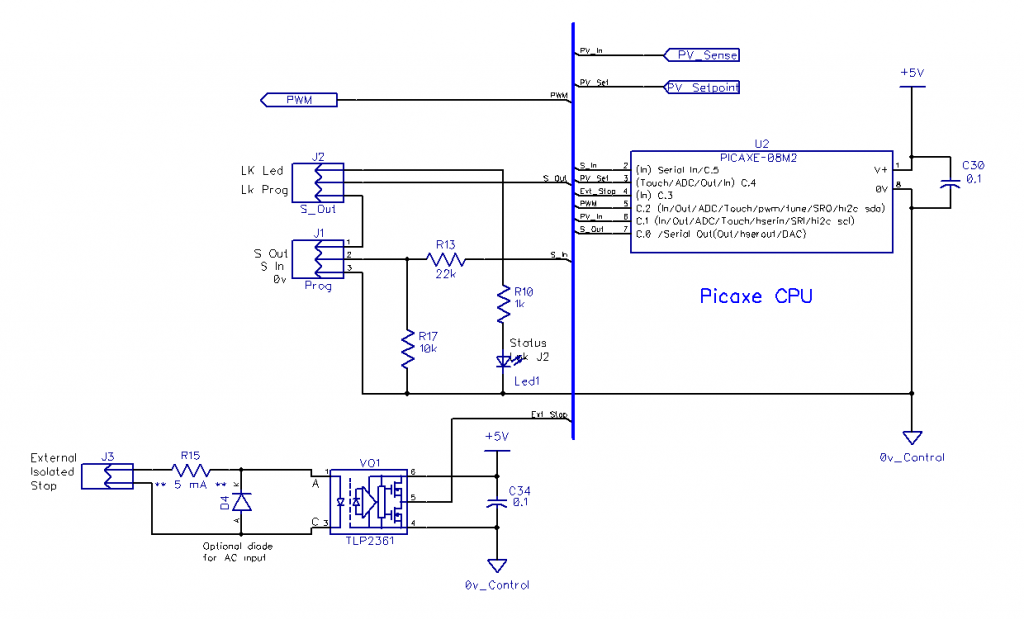 Minimal CPU control required, so have used a Picaxe 08M2, will play around with differing PWM frequencies, 32Khz has 1024 bit resolution, 64Khz 512bit etc; input voltage measurement about the set point isnt too critical, so will go with as high a PWM as I can get away with - (smaller Inductor). Will post amended PCB. Cheers Mike Edited 2022-01-24 09:12 by Solar Mike |
||||
| Clockmanfr Guru Joined: 23/10/2015 Location: FrancePosts: 437 |
Hi Mike, Brilliant, What you are doing is really needed. I have been watching your endeavours with great interest. When you said, "My previous designs for this have been too complex or not enough granularity in load control;" My eyes lit up. AS you probably know i am always interested in keeping things simple and robust. Sorry i can not actually do any work with you on this, but i have a heck of a lot of work and other projects on at present. But i will study your works closely and chime in when appropriate. Everything is possible, just give me time. 3 HughP's 3.7m Wind T's (14 years). 5kW PV on 3 Trackers, (10 yrs). 21kW PV AC coupled SH GTI's. OzInverter created Grid. 1300ah 48v. |
||||
| Solar Mike Guru Joined: 08/02/2015 Location: New ZealandPosts: 1228 |
Final PCB, same size 100 x 100, have sent gerbers off to be made couple of days ago along with a batch of other designs, they may be completed before Chinese N Yr holidays: 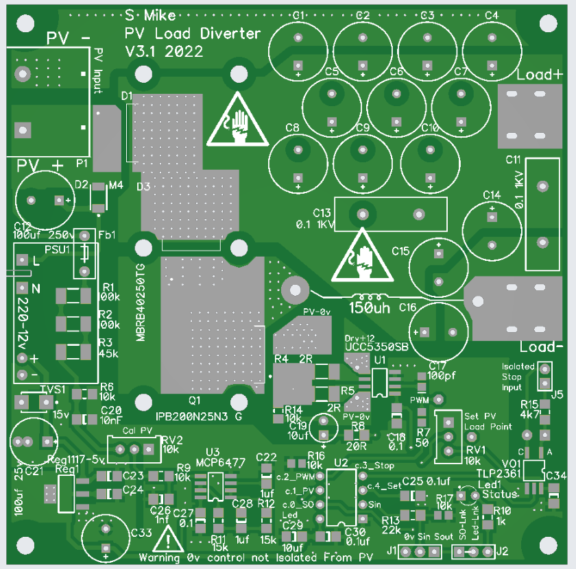  Here are the zipped gerbers, should anyone be brave enough to build one up AND write some Picaxe "Basic" code to run it, maybe a while before I get around to building it. Gerbers: PVLimiter3_0.zip Cheers Mike |
||||
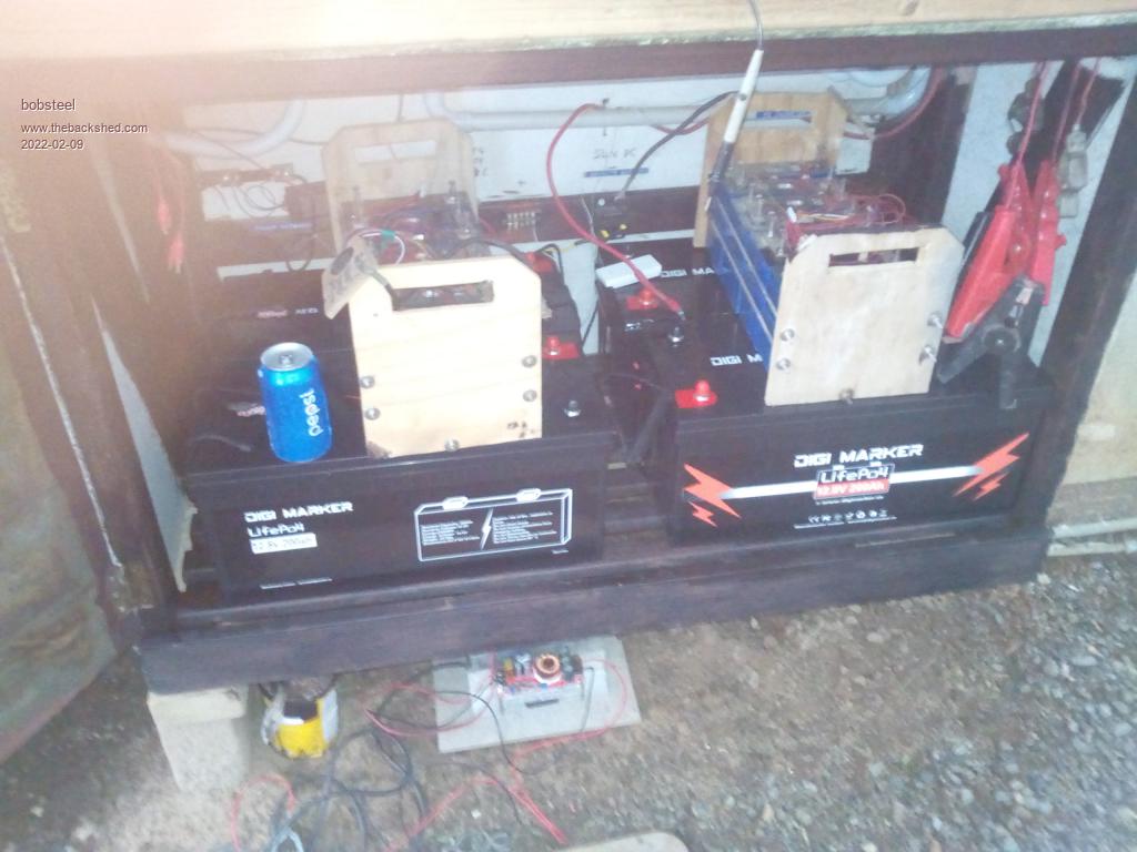
| bob.steel Senior Member Joined: 27/02/2020 Location: AustraliaPosts: 188 |
Seems to me you are focused on board designing and processor chip playing , rather than the water heater side of it . Its all important and its all interesting for which I thank you. But,I am still looking for something that works now to use excess PV capacity to heat my 240 volt water heater. Does anybody have anything I can build that actually works? My build ability is better than the majority having deep electronics , processor ,coding and electrical engineering skills and a couple of working inverter /battery systems running for years. Edited 2022-02-05 05:48 by bob.steel |
||||
| Solar Mike Guru Joined: 08/02/2015 Location: New ZealandPosts: 1228 |
What is the expected MPPT voltage and current for your array Bob, that will decide what may work OK. Cheers Mike |
||||
| Godoh Guru Joined: 26/09/2020 Location: AustraliaPosts: 678 |
Hi Bob, You may be able to cobble up something like I use. I use a Victron Smart controller (BMV712 , that measures battery state and has an inbuilt relay. The relay can be set to turn on and off at any state of charge. So I have mine set to turn on at full charge of the batteries then turn off at 97% capacity. I use the relay to switch a contactor that is connected to my inverter so that the inverter turns the water heater element on when the batteries are fully charged then off if they get down by 3%. I don't always need the booster as I have solar tubes for hot water as well as a wetback on my wood heater. The booster really only gets used on rare occasions so it is set up to plug in to a power outlet in my shed. Pretty manual but it works great. Seems like you have the skills to make something like that. Pete |
||||
| bob.steel Senior Member Joined: 27/02/2020 Location: AustraliaPosts: 188 |
well now there is a question . I have on one house 12 panels of 250 watts about 37 volts peak I think without going to a lot of trouble . 8 amps so at best I'm getting about 8 amps at 350 volts lets say. My inverter cuts charge when my batteries reach 54 volts and thats usually by about 10 am here. So the best hours 10 to 4 pm are just wasting .So my use would be turn water heater on when the battery gets to 54 volts and off when it drops to 53 volts I would say . But what do I feed to the water heater ? its 240 volts . |
||||
| bob.steel Senior Member Joined: 27/02/2020 Location: AustraliaPosts: 188 |
OK . I have voltage sensitive relays that will do that. I don't have a contactor of that amperage requirement but thats easy to get .however, My inverter is a hybrid connected to batteries and not the grid . It is also the charger . How is your inverter set up to keep producing 240 volts to send to the heater after the charging has been turned off? Am I understanding that when connected so the battery is driving the inverter ,or are the solar panels feeding the inverter direct and 240 volts then fed to the heater? Maybe both are doing so. Could you elaborate on that please. |
||||
| bob.steel Senior Member Joined: 27/02/2020 Location: AustraliaPosts: 188 |
Solar Mike Sorry the anti edit got me . I understand MPPT but don't see its relevance here. |
||||
| Solar Mike Guru Joined: 08/02/2015 Location: New ZealandPosts: 1228 |
The control mechanism I use to transfer power from the incoming PV to an external load uses the PV array Mppt voltage as one of the sense parameters. When under full load your PV charger will pull the incoming voltage to sit at or about the arrays stated Mppt setting, as the load comes off or the batteries get near full charge, the incoming voltage will start rising above the Mppt point, my circuit senses this and starts applying an increasing gradual load to the PV, diverting the power away for other purposes - like water heating. This extra varying load is seamless as it can go from 0 to 100% in 0.1% steps always attempting to keep the array PV voltage just above the stated Mppt value, it won't extract all the PV's power as it cannot go right to the Mppt point without affecting the existing PV controller. But this board isnt designed for such a high voltage DC, I would have to make it considerably larger to accommodate the extra spacing required between components and pcb traces, in fact the design would have to be altered to make it safe to use for those voltages. I can think of something way simpler that would work in your situation using capacitor discharge to divert power from the PV, will have a think about it.... If you already have an AC inverter in place, then having two voltage switches on the battery voltage turning on\off an ac contactor to connect your inverter output to the 230V HWC element would seem to be the simplest solution, may work?, depends on the bank AHr capacity and battery type; if lead acid the float voltage can drop significantly under any sort of high load like a 2kW heater, so your contactor would be forever cycling on/off. Cheers Mike Edited 2022-02-07 21:20 by Solar Mike |
||||
| Godoh Guru Joined: 26/09/2020 Location: AustraliaPosts: 678 |
Hi Bob, as my system if totally off grid it is a bit different to yours. My controllers feed the batteries directly, so when I turn the inverter on to use the extra power I don't need, the power comes from either the panels or battery. I have 5kw of panels and I have never seen the batteries take more than 2kw of power in. The internal battery resistance prevents them accepting more that around 100 amps. My system is 24 volts. So when the batteries are full and I put the hot water on the panels supply the inverter via the regulators.If the sun dips behind clouds then yes the batteries are supplying power to the inverter. The inverter is always connected to the panels via the regulators, and I have my relay set so that once the battery falls below 96% state of charge the relay turns off. That way I cannot accidentally drain the batteries. It would be good in a way to use an inverter like a Grid tie that connected directly to the panels to run the hot water, but then the other inverter would have to be on simulating the grid anyway so I don't see much advantage. Like I said the hot water system is an evacuated tube system, so when the sun is out it heats the water. It is only on cloudy days that I need to use solar backup and that is only in summer when the wood heater is not running. hope that is clear Pete |
||||
| bob.steel Senior Member Joined: 27/02/2020 Location: AustraliaPosts: 188 |
 Thats the bit that gets me ! The Mppt voltage is not set anywhere . It is a calculated figure per second or otherwise that tests the next point of voltage up and down to see if the current increases or decreases . If it goes up it moves the voltage to that step and checks the next step up and so forth until it reaches a vlotage at which point the current falls and that is the MPPT point for the time being . This is usually a routine on a microprocessor working at 100Mhtz or something . So what are you referring to when you say MPPT Please? The solar panels are about 37 volts 8 amps if thats what you mean. I have tried this unsuccessfully . Using a water heater 12 volt Element and a 24 volt element . I could not make it work in any fashion. I use a LFP 48 volt bank of 300 Ah. Edited 2022-02-09 11:42 by bob.steel |
||||
| Godoh Guru Joined: 26/09/2020 Location: AustraliaPosts: 678 |
Bob I don't know what is in the Victron BMV712 but It shows state of charge as a percentage of full, so I am guessing it is measuring power in and out of the batteries. Possibly a double pole relay would work. One connected in parallel with the inverter on/off switch to turn the inverter on. And one set of contacts to connect the hot water element to the inverter output. You would need some sort of time delay on the voltage measurement so that the element did not keep turning off and on. My hot water tank is only small (20 gallons) as there are only two of us here. I changed the element to an 800 watt element and it does the job fine for me. My system is simple, I look at the battery charge, check the temperature of the water in the hot water tank and if I want to boost the hot water heat, then I plug the element in and turn the inverter on. When the batteries go below 96% the BMV relay opens and the hot water element is turned off. Pete |
||||
| Solar Mike Guru Joined: 08/02/2015 Location: New ZealandPosts: 1228 |
The MPPT voltage is set by the manufacture see here on a panel I have here: Sure the CPU continually tracks this as the max power output moves about; around the manufactures spec values, changing with temperature and available sun light; the voltage doesnt change much however and I set my trip point a volt higher than the spec. 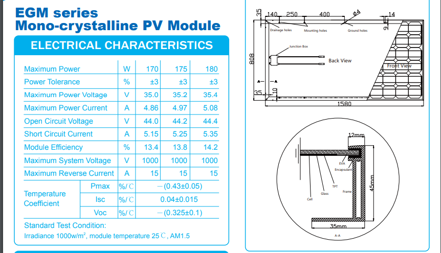 Cheers Mike |
||||
| Solar Mike Guru Joined: 08/02/2015 Location: New ZealandPosts: 1228 |
With Lifepo4 the voltage curve is so flat you cannot tell the state of battery charge by reading the voltage, so yeah attempting to do this by measuring the battery voltage isn't going to work. Best you could do is retro fit a coulomb counting energy meter with programmable switches, set to energize your water heater when say 90% and above battery capacity. Energy Meter I use one of the above on all my installations as an arbiter for "State of Charge" capacity of the bank. Cheers Mike Edited 2022-02-09 18:49 by Solar Mike |
||||
| bob.steel Senior Member Joined: 27/02/2020 Location: AustraliaPosts: 188 |
Well no I disagree . The Inverter/charger I use charges to a set point . 54 volts in my case then stops charging altogether. So when the charger stops charging the opportunity there seems like it could be used at say 54 volts on and 52 volts off . That part works fine . Its what do you do then that gets me . All I can see to do is the voltage relay turns on at 54 volts which turns on a 240 volt line from the inverters output side to the water heater. Has anybody got this working? I was not able to . On the MPPT The solar panel maximum power is not an MPPT refererence Mike sorry . You seem to have misunderstood that bit (or I have) . Maximum output voltage is when the panel is lit to the full and is coldest .that is the maximum voltage it can put out. Short circuit current is the maximum current it can put out. LFP Voltage Yes the capacity curve is fairly flat but readable and useable . When a cell gets to 3.4 volts ,say its a 100 Ah cell,the amount of energy required to get it to 3.5 volts is about a minute at 1 amp and 3.65 volts push. The resistance is such that you can barely get 1 amp into it and the current falls quickly .to half an amp at 3.5volts If anyone doubts this just try it on a small cell or whatever you can lay hands on. Put it on a lab supply 3.65 volts and don't bother to set the current . Turn it full up if the cell is at 3.4volts. If you have an 18650 Lithium Ion cell handy charge it to 4.0 volts and set the lab supply at 4.2 volts. It does the same to get to 4.1 volts . Edited 2022-02-09 21:45 by bob.steel |
||||
| Godoh Guru Joined: 26/09/2020 Location: AustraliaPosts: 678 |
Hi Bob, you said that at best you are getting 8 amps at 350 volts out of your panels. So why not just build a dedicated inverter to run off the power diverter. That way whenever the diverter is turned on the panels will feed power directly to the dedicated inverter for the how water. There may be a couple of problems. First there must be some sort of way of making sure that you are not back feeding into the grid if you are connected to it. Second the panel voltage will vary with clouds etc so the inverter will have to be fairly dumb. The element won't care if it is getting 240 volts or less, it will just heat less. All you need to do is convert the DC from the panels to AC to power the element, and disconnect the element from the grid while you power from solar. Pete |
||||
| Page 1 of 2 |
|||||
| The Back Shed's forum code is written, and hosted, in Australia. | © JAQ Software 2026 |
