
|
|
Forum Index : Solar : Active Battery Cell Balancer
| Author | Message | ||||
| Solar Mike Guru Joined: 08/02/2015 Location: New ZealandPosts: 1162 |
The battery cell balancing component for BMS solutions I have made in the past have all used resistive dump loads switched across any battery cells that are peaking in voltage higher than others; in top balancing systems (typical house banks). This works fine on small isolated battery packs, not so much on multi-KWHr banks where the charge currents maybe very high and concurrent heavy loads. Switching a 1--2 amp load across a 400 AH lifepo4 cell when its being charged possibly at many amps near its knee voltage 3.47 to 3.5 volts makes little difference to lesser capacity cells that are peaking higher than others. I have a set of odd cells here that are of different manufactures and capacities, I want to make up a 48v bank from these, their capacities vary 20 AH apart and so a better top balance scheme is required. I did look at those cheap multi-cell active transformer balancer units that output to the next cell in line if there is a voltage difference between any two cells > 0.1v. They do work with an amp or so current at larger cell differences, lesser current for closely matched. Again too small for large packs. Thought I would have a play with a system that uses an isolated fly-back inverter on each cell that loads the cell up with 5-10 amps and outputs to the whole bank. I have some small ferrite cores here and other components on hand to play with. The test circuit uses a variable duty cycle oscillator at 100 khz to drive the fly-back converter, its duty cycle manually set for the required load current - no feedback. Difficult to breadboard something like this, good layout is required, so have gone straight to a small pcb 50 x 100mm for testing on a single cell; if it doesn't work, well it was cheap to build. Because the cell voltages are lower than the min required voltage for mosfet drivers, have used a small thumb sized boost module to up the driver voltage to 12v and run off that. Here is the schematic: 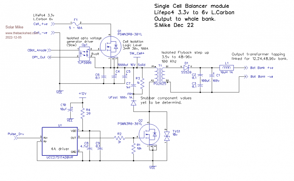 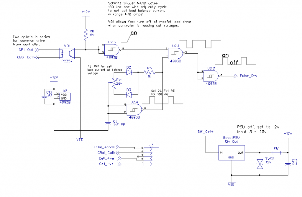 More to follow... Mike |
||||
| Murphy's friend Guru Joined: 04/10/2019 Location: AustraliaPosts: 671 |
Interesting, Mike. I'm just building an active cell balancer that warpspeed (who unfortunately no longer posts here) came up with. It's a very clever design that also uses inductance to balance large lipo cells. Mine will be for a 200Ah/ 48v nom. cell bank. The PCB's are on their way presently, once I have everything ready for testing I'll let you know how well it performs. |
||||
| Solar Mike Guru Joined: 08/02/2015 Location: New ZealandPosts: 1162 |
That's good, I haven't seen his design, has it been published anywhere? It might work out better than what I'm trying now. Cheers Mike |
||||
| Solar Mike Guru Joined: 08/02/2015 Location: New ZealandPosts: 1162 |
Here is the test pcb, two fit on a 100x100 pcb. 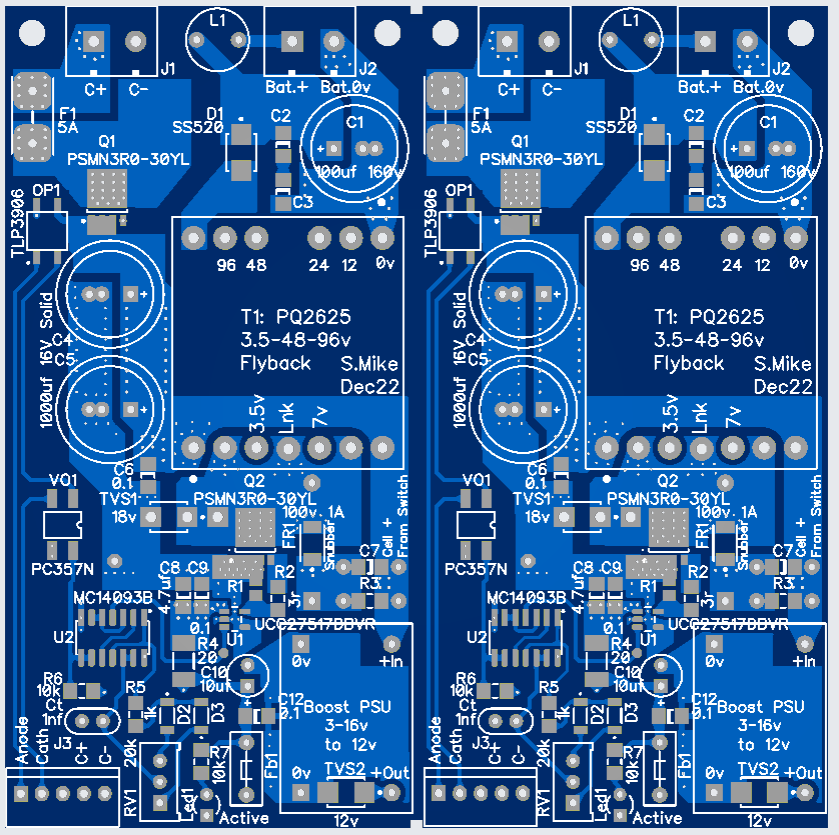 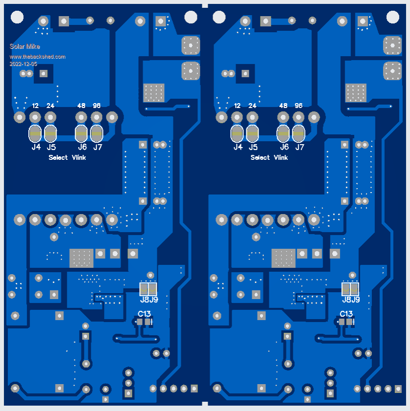 Edit: For anyone whom wants to experiment, here are the gerbers for the pcb, 2 pcs on a 100 x 100mm board. If you get them made 1.2mm thick, can easily score with box cutter both sides and snap in half. Gerbers_TestFlyback.zip Cheers Mike Edited 2022-12-05 14:48 by Solar Mike |
||||
| Murphy's friend Guru Joined: 04/10/2019 Location: AustraliaPosts: 671 |
I don't know if he published it, doubt it since it's not yet at the final stage. Tony's balancer is for 30 cells, I'm making one for 16. I'm sure it works better  , being a creation from the master himself. , being a creation from the master himself. |
||||
| nickskethisniks Guru Joined: 17/10/2017 Location: BelgiumPosts: 462 |
For me, Solar Mike is one of the masters too on this forum :p Mike, I like your idea, is their a reason you didn't take an IC like those uc38xx style chips for the flyback? Then you can have a fixed or maybe variable current, and are not dependable on the load (12V or 48V battery or what ever voltage, because current is fixed). Would there be a solution to get rid of the extra 12V psu by adding an auxiliary winding? Or/and adding an extra opto for voltage feedback, if the output was not loaded the output capacitors could blow up. Just food for thought. |
||||
| Solar Mike Guru Joined: 08/02/2015 Location: New ZealandPosts: 1162 |
I didn't have any of those generic uc38xx chips on hand, so opted for this design, which may be more complex than it needs to be, I also wanted to totally remove the load off the battery cell when not required. Yes there is no current or voltage feedback which may be detrimental to its operation; time will tell. I have the pcb's and the ferrite cores + most other bits, waiting on Element14 for the mosfets, they have them in stock but no sign of them after 3 weeks post order. Possibly, those tiny non-isolated boost converter psu's are the size of my thumb nail and will step up from 2.5V to 12V, so will work on 3.3V Lifepo4 and 6V Lead Carbon batteries. I anticipate possible fireworks getting it working... It will have to always be connected to the main battery pack as a load. I also have another more simple design using a self oscillating flyback boost mosfet stage, will play with both. Have a great New Year Everyone. Cheers Mike Edited 2022-12-31 20:47 by Solar Mike |
||||
| Murphy's friend Guru Joined: 04/10/2019 Location: AustraliaPosts: 671 |
Mike, just to let you know that I finished building Tony's (warpspeed) design lithium cell balancer. Its working on a single cell at the moment, have to make up all the other connecting wires yet. I'll post a separate thread when I got some results with a full 16 cell bank. |
||||
| The Back Shed's forum code is written, and hosted, in Australia. | © JAQ Software 2025 |
