| Author |
Message |
Murphy's friend

Guru

Joined: 04/10/2019
Location: AustraliaPosts: 674 |
| Posted: 10:59am 03 Jan 2023 |
 Copy link to clipboard Copy link to clipboard |
 Print this post |
|
While warpspeed is no longer posting here, he kindly shared the design of this balancer with me. And it's a real clever bit of work, too much electromagnetic trickery going on for me to fully understand.
But it works! Today I finally got everything ready to test it on my old 16 cell Winston battery bank (200Ah cells). Half of the cells are 10 years old and the other half 5 years old. I could never completely balance these using my Deligreen balancers when that bank was still in use.
Its been sitting around for a year or so, getting charged occasionally. I estimate there is 50% capacity left in these cells, so an extra 5KW of battery bank would be welcome to add to my 2 x 10KW banks.
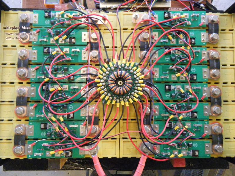
You might ask by now what Warpspeed's balancer looks like, well, like something that came from the deep blue and crawled on top of my battery bank 
See for yourself:
How does it perform? Very well so far at this early testing stage.
For the test there is no load connected to the bank nor any charger, it's just the battery bank powering the balancer.
Initial reading was a max cell voltage difference of 310mV.
After one hour that dropped to 160mV
After two hours it was 110mV
3 hours later it was 100mV
5 hours later it weas 70mV
It's now balancing overnight, I'm curious when it gets to perfect balance of 3.37V/cell.
After that it's going on the charger to see how that goes.
The balancer's electronics consumed 33mA at the 5 hour test, this was a little higher at start up.
The balancer is deadly quiet and nothing got warm even on this 36 degree day here in Perth.
I'm happy with it so far, it's not a cheap solution, probably similar cost than a 16 cell Deligreen balancer due to the many parts required. But it was a very interesting project, I'm grateful for warpspeed's help during the building time.
Anybody interested in more details let me know, there are a few tricks involved setting it up. Messing about on top of 200ah cells can be 'exiting' if something goes wrong. |
| |
nickskethisniks
Guru
Joined: 17/10/2017
Location: BelgiumPosts: 474 |
| Posted: 12:05pm 05 Jan 2023 |
Copy link to clipboard |
Print this post |
|
Mmm, interesting, makes me wonder which components that are used, and how it works. I see only 1 mosfet/module?
So you have a signal (pwm) running to each module feeding an optocoupler/ mosfetdriver, so they modules are synchronized. This is provided nu another pcb, not on the picture? And they other ic on the modules are separate boost ic's to provide power to the mosfet driverstage?
Energy is exchanged by the toroidal transformer. Just guesssing around.
What's the value of the glass fuse, they tend to have a high resistance, you might limit the current with this fuse.
Looks really Nice! |
| |
Murphy's friend
Guru
Joined: 04/10/2019
Location: AustraliaPosts: 674 |
| Posted: 03:02pm 05 Jan 2023 |
Copy link to clipboard |
Print this post |
|
Thanks Nick,
I'll post more pics soon. The other PCB is under the toroidal board on that picture, that wasn't a good place as to get at it everything had to be disconnected  . That board is now on top. . That board is now on top.
Your guess is good, the toroid's 16 turn primary is driven by a 40KHz square wave. There is a 16 turn recovery winding as well.
Each cell board is powered from a single turn secondary, so each gets exactly 1/16th of the battery voltage (16 cells).
I'm aware about the fuse' resistance (10A) it's there for set up & testing. Now the glass fuse is replaced by a tinned 5x3mm copper bar.
Absoluter minimum resistance is essential for the secondary part. I use 4mm sq wires and fat tracks on the PCB. The toroid board is 2oz copper, beefed up with copper wire on the bottom as the tracks form part of the single turn secondary. |
| |
Murphy's friend
Guru
Joined: 04/10/2019
Location: AustraliaPosts: 674 |
| Posted: 06:32am 06 Jan 2023 |
Copy link to clipboard |
Print this post |
|
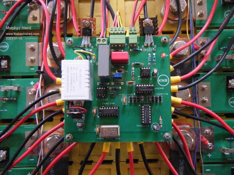
Here is a picture of the power/ control board. The leading/trailing adjustment is for sync dead time so the cell board mosfet only turns on after the secondary switching spikes have settled.
 |
| |
JohnTaves
Newbie

Joined: 01/11/2023
Location: United StatesPosts: 19 |
| Posted: 02:28am 04 Nov 2023 |
Copy link to clipboard |
Print this post |
|
I don't understand the utility of all this complexity. It seems like complexity added to overcome a poor architecture.
1) Balancing the cells when they are not near the top of their charge is rather dubious because the voltage in the middle of the state of charge is very flat. I think it is a mistake to waste time worrying about one cell being at 3.37 and another at 3.30. I suspect this is finding meaning where the data is providing no such thing.
2) My thinking is that the real issue is that one cell might always be the one that reaches the max V before the others. I figure the lithium cell suffers a bit of abuse each time it reaches the max V, and if one cell is above the others, it will get abused while the others are not. Not to mention the lower pack capacity from having one cell above the others.
3) Most BMS are a combination of a disconnect circuit and the brains that measures the cell voltages. Then the chargers and loads will monitor pack voltage and stop charging or stop loads when the pack is too high or too low. This architecture is just plain wrong. The excuse for having the charge/no charge logic operating from pack voltage is the legacy from lead-acid. This architecture forces you to have balanced cells, so that no single cell is at the max V before the whole pack reaches the threshold.
The solution is two fold. First use a BMS that sends a charge/no charge and load/no load signal to your chargers and loads. In other words, don't rely on pack voltage to determine if it is OK to charge/drain the pack. Second, connect a resistor across the cell that reached the max V, causing charging to stop, and leave that resistor on for several hours. I mean leave it on regardless of whether the pack is charging or discharging. Then repeat this until you have gotten each cell to be the first to the top. Repeat it over the life of the pack.
Edited 2023-11-04 12:28 by JohnTaves |
| |
Murphy's friend
Guru
Joined: 04/10/2019
Location: AustraliaPosts: 674 |
| Posted: 06:56am 04 Nov 2023 |
Copy link to clipboard |
Print this post |
|
Hmmm, I have a suspicion you do not really understand how the above balancer works.
However, you do it your way and I do it my way, shall we leave it at that. |
| |
