
|
|
Forum Index : Solar : Solar hot water, me too
| Author | Message | ||||
| Murphy's friend Guru Joined: 04/10/2019 Location: AustraliaPosts: 671 |
The recent post of a solar hot water system has inspired me to build one too. Hot water here comes from an instant gas heater, it works well (no pilot light used) but its getting old and might require replacement in the near future. So I installed 12 x 190W (2.2KW) second hand mono solar panels which are connected as two 6 panel strings. These 6 panel strings give me a 210V MPPV, close enough to power a 230V water heater. The controller was build from information posted here with the addition of the solar power being re directed to a 2KW GTI once the hot water element thermostat turns off. That GTI is connected to my mini grid (NOT the street power - I'm off grid here) to be available for general AC power or battery charging via my inverter. Another feature was the addition of an analog 10A panel meter, monitoring the solar current, beside the usual flashing neon light. Here are some pictures of this build: 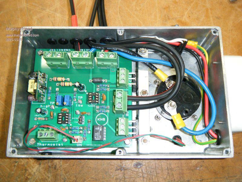 For the capacitors I re cycled 16 off 470uF/450V, giving me around 7500uF in total. 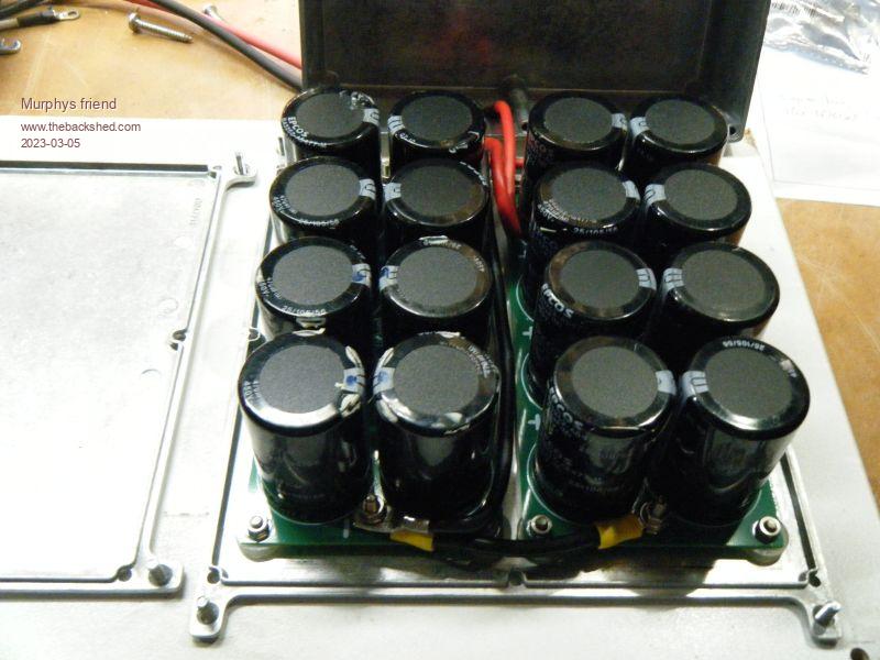 Both were enclosed in metal cases to contain possible high Volt DC fireworks  . .All is bolted to the wall next to my off grid power equipment. 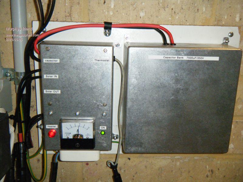 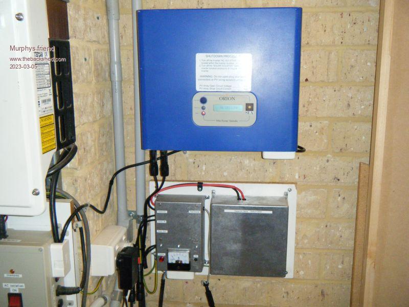 Testing was done initially on the bench with a variable high volt DC supply. First I set the low and high volt trip points. With the optimal MPPV being 210V I choose a smaller than usual range to cycle around that voltage but stay below the open circuit voltage of the string. So it was set to 195V for the low and 225V for the high point. I then adjusted the DC supply to 210V, connected a 150W flood light as load, simulated an ON thermostat and switched the DC to the controller's solar input on. Nothing happened, the floodlight stayed off. After a while of head scratching the penny eventually dropped when I realised the DC voltage has to be at the upper trip point to turn the IGBT on  . .Cranking the supply up to 225V, the lamp started cycling on and off as expected. My DC supply voltage is rectified AC via an isolated Variac of only 500W capacity. Next everything was installed on the wall and connected to my solar panels. This time I used an older type whistling kettle (1500W) as load as its thermostat only cuts out when it boils dry. I inserted the NTC sensor of my 12V thermostat and a thermometer in the kettle's spout and turned the solar power on. This time no cycling, the Amp meter showed 6A, with obviously plenty of solar power available just then, and the kettle soon got hot enough to make the thermostat turn the controller off. 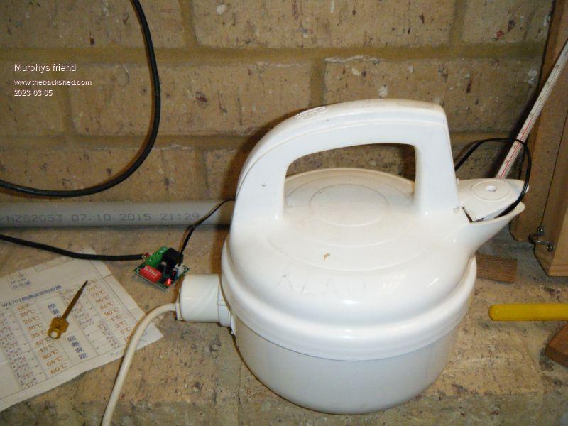 So its working (with a kettle anyway), but I still have to complete the power wiring to the hot water heater and install that as well. An interesting project, I enjoyed building it. BTW, I used a low Ohm resistor to completely discharge the lethal potential of the capacitors each time before I worked with them, something to consider for anybody planning to build this controller. |
||||
| Godoh Guru Joined: 26/09/2020 Location: AustraliaPosts: 530 |
It looks very neat. Just a query , how is the thermostat in the hot water system going to handle DC. Won't it arc too much when it turns on and off? Pete |
||||
| phil99 Guru Joined: 11/02/2018 Location: AustraliaPosts: 2608 |
" how is the thermostat in the hot water system going to handle DC. Won't it arc too much when it turns on and off?" If it were straight 210V DC it would arc until the thermostat is incinerated. If the controller pulses it often enough the arc might be extinguished before that. A thermistor clamped to the tank beside the thermostat, shutting down the controller at a slightly lower temp than the thermostat would be safer. Same as the kettle setup. Edit Looking more closely at the photo of the PCB it appears the thermostat doesn't switch the 210V directly, if so ignore the above. Edited 2023-03-05 14:26 by phil99 |
||||
| Murphy's friend Guru Joined: 04/10/2019 Location: AustraliaPosts: 671 |
Pete, the thermostat just switches 12V DC. Here is the schematic so you can see how it does that:  |
||||
| Godoh Guru Joined: 26/09/2020 Location: AustraliaPosts: 530 |
Looks great, that will definitely fix the arching problem. After reading your post on your build, I was thinking of making something like it too. Then I realised that my Victron BMV had a relay in it that I have been using for my manual hot water control. So I set the voltage points on it, and used another relay to turn my shed inverter on and off between those points. Now my hot water system works automatically too. It is a solar hot water system with a Wet back in the wood heater for winter, now it uses excess solar power to the element too. I have an electronic thermostat on the tank that turns on a relay to power the element, now a second relay also starts the inverter. I tried to get my head working on arduino again, ( have not touched that stuff for years now) but it was fuzzy ( my head that is). So I reverted to relay logic. Pretty easy for my head to get around. Your controller looks great. I only run my panels at 70 to 90 volts DC so it would not work for my system. High voltage DC scares me a bit after working years ago on valve guitar amplifiers and blowing up a couple of multimeters on them. Cheers Pete |
||||
| phil99 Guru Joined: 11/02/2018 Location: AustraliaPosts: 2608 |
No! Your head is fine, the Arduino language is weird. Re. the Wet Back in the wood heater, long ago had one of those. It eventually rusted out, a replacement was much too expensive so replaced it with a slab of fire brick. The efficiency of the heater went up dramatically, saving tons of wood. After winter we noticed the hot water power bill was much less than previous years, it should have been more. Did a bit of research and it turns out a Wet Back fire box cools the fire too much resulting in incomplete combustion. Half the fuel is going up the flue as unburnt gasses and soot. Power was also being wasted when the wood heater is not used as the thermosyphon effect reverses, taking heat from the tank to the Wet Back. I hope your system is better than that! A better setup would have a heat exchanger after the fire box and use a thermostat controlled circulating pump rather than thermosyphon. |
||||
| Godoh Guru Joined: 26/09/2020 Location: AustraliaPosts: 530 |
Hi Phil, the heat exchanger idea sounds good. I did have a copper coil wound around the flue on one heater, it worked pretty well. Fortunately our house is tiny and we only run the heater during the day in winter as the house gets too hot for sleeping at night for us if we keep it running. The wetback can boil the water in the hot water tank also if we leave it running too long, there are only two of us and so we only have a 100 litre hot water tank. If the wet back dies, I may change the system and see how your idea goes, I do have a couple of small pumps that would do the job, and still have the coil for the flue. Cheers Pete |
||||
| KeepIS Guru Joined: 13/10/2014 Location: AustraliaPosts: 1872 |
Nice work, I have not used one cent of mains power for hot water since building and installing mine. Except for the big Wall Oven we are almost off grid. The 10 year old feed in inverter and panels are left in tact and sending everything they get back into the grid, when they kill the feed in tariff rebates that system will be stripped and added to the off grid system. NANO Inverter: Full download - Only Hex Ver 8.1Ks |
||||
| Murphy's friend Guru Joined: 04/10/2019 Location: AustraliaPosts: 671 |
Thanks Mike, I'm looking forward to get my hot water heater ready, still a while before I finish the power cable for it (requires ripping up pavers & digging a trench). Now, the eagle eyed of post scrutinisers here  might have noticed there is an error in my schematic. Unfortunately it missed my double checking. might have noticed there is an error in my schematic. Unfortunately it missed my double checking.As shown, the controller only supplies solar power to a connected GTI while the heater is on. What is wanted is the opposite. Just remove the connection from the 12V relay coil to its center contact. Then, connect that center contact directly to 12V. Fixed |
||||
| Murphy's friend Guru Joined: 04/10/2019 Location: AustraliaPosts: 671 |
An update; This hot water controller has been working very well for 4 weeks now. On sunny (Winter) days the thermostat switches off around noon, on a recent rainy day, when heavy overcast, it still managed to get the water very hot but not quite hot enough for the thermostat to open. I'm happy with that system. Matching the panel string max power voltage to the control trip point *is* important as is the element wattage. Having that analog Ampmeter was a much better indicator of the power being fed to the element as the original neon light is. My 160 liter hot water storage unit normally comes with a 3.6KW element but, having only about 2KW of solar panels, I got it with the optional 2.4KW element. Improvements could be using 7 panel strings which would raise the MPPV to around 250V instead of the 210V I have now. For those wishing to build this without the solar power diversion feature (once the thermostat opens) just delete the relay and the extra IGBT in the schematic above. |
||||
| RFburns Regular Member Joined: 21/07/2017 Location: AustraliaPosts: 43 |
Hi would the Gerbers or .pdf board/track layout be available please?. RF Edited 2023-07-16 20:16 by RFburns Strong like horse smart like tractor! |
||||
| Murphy's friend Guru Joined: 04/10/2019 Location: AustraliaPosts: 671 |
Where are you located? I may have a spare set of boards. |
||||
| RFburns Regular Member Joined: 21/07/2017 Location: AustraliaPosts: 43 |
Hi I am in Central QLD, PM me (I seem to be having trouble with PM at the moment). If you have a set of boards let me know please. Strong like horse smart like tractor! |
||||
| RandomActs Newbie Joined: 23/07/2023 Location: AustraliaPosts: 1 |
My 180 litre hot water system works well. Two strings of 3 x 260Watt panels provide about 90V DC@ about 18A into a 1.9kw heater element that was a 48V model but moved the 2 links to be a 90V element. Probablly best resistance matching. I did some experiments to evaluate the 90 V and discovered the 3 panels as described Didn't want to burn up the contacts of the existing mechanical thermostat with DC current so it only handles 12v @ about 100ma to switch the input of a D.C. Solid State Relay rated about 40A DC x 400V Dc. Cheap. A main 25A isolating CCB in series, and a very small c/o switch controls the SSR on, or bypass the thermostat. Regardless of any thermostat hysteresis it is set for 95degrees and of course a tempering device is on the output that mixes cold with the very hot water to give about 40 degrees max at the output. I didnt trust the old thermal insulation to take advantage of the higher stored level of thermal mass so took the tank out of its old steel drum and replaced it with good R factor closed cell thick foam rubber sheet insulation. The SSR is mounted on an ordered heat sink and only needs backup 50V supply about twice in 5 years. Small gas shower heater is on standby. The small bypass switch will easily take the temp up another 5 degrees to boil the tank. Is still ok after 5 days of set in rain for shower being a bit careful with usage, and the return of partial sun can be a bit slow to recover tank temp to above 40 degrees shower water temp but would be helped with another string of 3 panels. No copyright. :-) |
||||
| Confused Newbie Joined: 02/05/2023 Location: IrelandPosts: 17 |
Hello everybody. I have a PV Solar Array set up here In Ireland. It has 10 #Bauer 420 W BiFacial Solar Panels. I'm just wondering has any of you set up a system for just heating your CH radiators. I understand that that will not be you're requirements In much hotter parts of the world but here In Ireland heating bills are the costliest. If any of you has done something like It or has an Idea. Any chance you could show me a method with the least amount of gear. Thank you. |
||||
| Confused Newbie Joined: 02/05/2023 Location: IrelandPosts: 17 |
I have my PV Solar array up and working. Presently only have it preheating my Rads. Grid tied thermo switch fitted. Can anyone suggest a means to protect my small preheat water tank in the event of the grid or pump power failure. I have a PRV fitted but I would like to extra protect and fit some sort of switch on the water tank or elsewhere to cut off the power from the panels in the event of power cut or the pump fails. Thanks |
||||
| The Back Shed's forum code is written, and hosted, in Australia. | © JAQ Software 2025 |
