
|
|
Forum Index : Solar : Wanted - anemometer that works sometimes.
| Author | Message | ||||
| Gizmo Admin Group Joined: 05/06/2004 Location: AustraliaPosts: 5036 |
I didn't think my drawing was that bad! Its a unidirectional wind switch. The plastic balls hangs on a brass wire, which is passing through a brass eyelet. Normally the ball hangs down, and there is a open circuit between the brass eyelet ad brass wire. When the wind picks up, from any direction, the ball is pushed sideways. If the wind is strong enough, the brass wire makes contact with the eyelet and you get a closed circuit, "Warning, wind speed alarm!!!" You can adjust the wind speed it triggers at by changing the brass wire lenght or adding weight to the ball. Glenn The best time to plant a tree was twenty years ago, the second best time is right now. JAQ |
||||
| GWatPE Senior Member Joined: 01/09/2006 Location: AustraliaPosts: 2127 |
Hi Gizmo, I think you mean, an "omni" directional wind switch. All directions, rather than "Uni" meaning one. Gordon. PS: I think it would work OK. become more energy aware |
||||
| neil0mac Senior Member Joined: 26/12/2009 Location: AustraliaPosts: 210 |
And if you want to be real fancy (a two stage warning system), you can use a larger loop lower down for "Cyclone!" Lurvelly. Now to add a 'vibration sensor' that draws a wire mesh screen over the panels for Gordon's hail stones, and we're all set. :-) |
||||
KarlJ Guru Joined: 19/05/2008 Location: AustraliaPosts: 1178 |
I worked out your switch was good for all directions just I had the same concern as Gordon re survivability in extreme weather, if its windy enough and associated with a storm the likelihood of hail is also there thus the parking, in my opinion is a moot point unless you can "park" it in the garage! Luck favours the well prepared |
||||
Loomberah Regular Member Joined: 11/06/2008 Location: AustraliaPosts: 43 |
Very large hail (>35mm that might cause PV panel damage) coinciding with very strong wind is likely to be a very rare occurence for any particular location. In any case, if it did coincide, flat panels are as good as any orientation, since the hail stones will not be falling vertically. I'd expect them to be coming from the NW-SW direction around here (where Neil and I are, NW slopes Wx district) in 99% of cases. I've considered putting a bird netting cover over my panels on days of hail storm risk, it would be a fairly minimal reduction in output for the day for a bit of peace of mind. I use a vertical spring mounted omnidirectional wind switch that works quite well, to slew my panels horizontal in big wind. Loomberah weather +solar&UV, astronomy, photography, organic farm |
||||
| KarlJ Guru Joined: 19/05/2008 Location: AustraliaPosts: 1178 |
cool lets see the pics Luck favours the well prepared |
||||
| neil0mac Senior Member Joined: 26/12/2009 Location: AustraliaPosts: 210 |
He has actually posted pics, and a video of the array in action - but you'll have to wait till he provides the link, |
||||
| Loomberah Regular Member Joined: 11/06/2008 Location: AustraliaPosts: 43 |
This was what I cobbled together initially with things I could find at the time, but I have replaced the spring with a new one and the plastic container on top now. It cuts in with a gust of ~40km/hr that lasts a couple of seconds. Contact is made between a brass tube over the top of the bit of wooden dowell and the gal saddle. 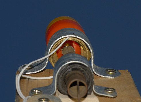
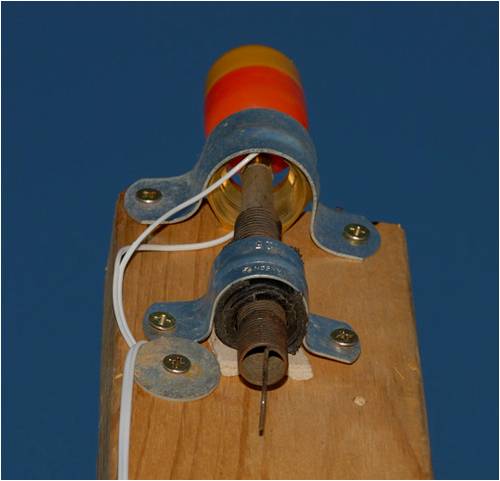
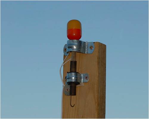
Loomberah weather +solar&UV, astronomy, photography, organic farm |
||||
| Loomberah Regular Member Joined: 11/06/2008 Location: AustraliaPosts: 43 |
The tracker in action is here: Equatorial Tracker in action Loomberah weather +solar&UV, astronomy, photography, organic farm |
||||
| vasi Guru Joined: 23/03/2007 Location: RomaniaPosts: 1697 |
Is looking as a sail to me. Risky! Hobbit name: Togo Toadfoot of Frogmorton Elvish name: Mablung Miriel Beyound Arduino Lang |
||||
| Loomberah Regular Member Joined: 11/06/2008 Location: AustraliaPosts: 43 |
It automatically parks horizontally (along the top edge) when its getting too windy (over ~40km/hr), and very strong wind (90km/hr+) is very rare anyway around here, in my experience < once per year. It has more panels on it these days too... Loomberah weather +solar&UV, astronomy, photography, organic farm |
||||
| neil0mac Senior Member Joined: 26/12/2009 Location: AustraliaPosts: 210 |
Gizmo! I thought it was a fine effort the first time that I saw it. But it has a severe limitation which is not your 'fault'. It doesn't indicate wind direction. (OK, so I didn't put that in as one of the criteria. I should have asked for an 'anemometer' that only works sometime (more precisely when the wind is blowing in a 'certain direction' above a given speed). The 'direction' however is a not a compass point but whether it is 0 or 90 degrees to a solar array. Here is 'THE' solution, I think !! Instead of having a fixed frame for a 'wind alarm' I want to place it on a hinge arrangement so the pin is parallel to the plane of the array. If I then deform your circular wire loop into an eliptical shape (with the major axis along the same alignment) I end up with an alarm that ignores 'cyclones' when they are hitting the array end on, but gives the picaxe a wake up call when blowing something approaching 'square on' to the array. Actually, the 'loop' needs to be segmented so that the microprocessor can decide what angle the wind is coming from, and react gently (slowly or with a delay) or rapidly if needs be. Probably the segment(s) near the end of the major axis can be left un-monitored as the tracker already has a satisfactory wind orientation. This also caters for a strong wind that changes the direction it is blowing from as the wire to the 'plastic ball' needs to progressively move less to make contact with the elipse at its minor diameter as the wind swings round. I think this also gives a greater tolerance between being inactive and functioning. When this happens, the array is turned so that the wind is more 'edge on' to it. That should give less opportunity for hail damage also. Thanks, Gizmo. You have helped me complete my tracker design (and removed the need for a number of additional expensive bits (one motor and now, no actuators). 'Locals', as defined below, can now safely build a 10KW two tracker (each being dual axis 5KW 'nominal') PV system driven by one electric (1/4/HP) motor for around $25,000 (after cashing in the RECs) with an output of 'up to' 80 ( perhaps 100? ) KW Hrs per day. Having learned of a major company in NSW that will pay $0.68 a KW that will give a very nice monthly income - if I can make the switch from Country Energy after it is up and running!. (And it should be still be generating something around $700 a month income in six years time - allowing for a doubling of current power prices, an annual increase for 5% p.a. over a 'fictitious' 50Kw Hrs daily consumption in the first year. I also expect to reduce the panel degradation from 1% a year to (maybe) half (or less?, the data coming from a very comprehensive spread sheet.) Magnifico ? I know many will say, "It can't be done, (especially for that sort of money)". You will be joining a long line of people who have told me that before and I would dearly love to prove them wrong. What is more, I have 'provisional orders' for 1 to 2 containers of panels from locals (within 20Kms) wanting 'in' on this deal as the panel price is roughly about 1/2 of retail. General details will probably be made available in due course (early to mid 2011?), when I have the proof of the pudding - and, to suit my other goals. This can still come unstuck in regards to costs IF ... the US defaults (or world economy collapses), the PIIGS don't keep flying or the Chinese re-value the yuan. |
||||
Bryan1 Guru Joined: 22/02/2006 Location: AustraliaPosts: 1211 |
The major problem I see with using a ball as a pv sensor that will park panels is birds, when a magpie spots it it will come to check it out, then the panels move he flies away, 10 minutes later he decides it's safe to go check it out again....... you finally get the alarm to find the actuator is burnt out from constant parking- unparking but wait don't forget inquisitive kittens either.... |
||||
| neil0mac Senior Member Joined: 26/12/2009 Location: AustraliaPosts: 210 |
I am using Gizmo's concept - not his scale drawing. Can't imagine either happening. I have yet to see a maggie push a hanging ball 200mm sideways, and hold it there for 2 seconds, nor kittens that can jump 2 1/2 metres vertically. |
||||
| GWatPE Senior Member Joined: 01/09/2006 Location: AustraliaPosts: 2127 |
On what a Magpie is able to do. I remember Magpies pulling roofing nails out of the roof, on a house I used to live, in the country. We replaced them with roofing screws and this helped keep the roofing sheets in place. Birds break director bars OFF the TV antennae as well. Gordon. become more energy aware |
||||
| neil0mac Senior Member Joined: 26/12/2009 Location: AustraliaPosts: 210 |
As per the OP, it only operates anything when the wind exceeds a given value and is coming from a substantial angle to the array. 

This 'Wind sensor' can be added to a rotating (dual axis) tracker and always maintain its position relative to the face of the array. (I don't need a 'compass point' reference for it to be useful.) The 8 contacts (segments A to H) give an indication of wind strength and direction to a PicAxe chip for processing. |
||||
| neil0mac Senior Member Joined: 26/12/2009 Location: AustraliaPosts: 210 |
Calibrating the beast. If I can determine the angles below, I should then be in apostion to design the sizes (height of pivot point above the ellipse, and the dimensions of its major and minor axes), and overall shape if something other than an ellipse (like an oval) is needed. I don't have 'reasonable' access to a high wind area. (Rarely do our wind speeds reach 50KPH, like as little as once every two months, but the 'powers that be' dictate that allowance must be for winds 'up to 140KPH.) The only way that I can see of setting the wind sensor up is to stick a LONG bit of RHS steel out of a vehicle window with the ball hanging down in front of a large (upside down) 'protractor', go fo a drive and record the angle of the wire at various speeds. (Don't have trffic congestion out our way as I can drive to town and not see another car in 16Kms.) (And, do I need to supply an illustration?) But there are other questions that may arise. 1. The pressure wave from the front of the vehicle. 2. Undulations in the road surface which, although tarred, doesn have noticable bumps and hollows tahy could cause inwanted forces on the ball. (I have yet to determine at what speeds these are most apparent in the movement of the vehicle so will keep close to the crown of the road when the road base is less affected by water from run off. 3. The mass of the ball. (A simple plastic ball will be too light to give a suitable range of angles? I only need 'readings' for speeds between 50 (40?) and 80(100?) KPH as lower speeds will not be a problem and the higher speeds will already have aligned the array with the wind direction. I will probably start with a plastic ball with holes at the top and bottom that can be sealed so that water or sand can be added/removed to increase/decrease the total weight (mass) and reduce the tendency to 'flap in the breeze' or hang too vertically at higher speeds. 4. The question of 'swirling winds' has been raised with me but from my research 'gusty type' winds only add about 40 KPH to the underlying wind speed - even in a cyclone - the wave on a swell analogy for water. So, over to the 'armchair critics' and the experts for your opinions. Thanks. |
||||
| GWatPE Senior Member Joined: 01/09/2006 Location: AustraliaPosts: 2127 |
Hi neil0mac, I gather there are no planning approvals needed for this venture. An engineer would put a case forward that if the mechanism fails in the worse posible wind position, that the structure still has to be strong enough to survive the maximum expected windspeeds in that position. Similar problems were faced by engineers designing houses for cyclonic conditions, where the winds can be +250kph You have mentioned windspeeds from 40kph to 140kph. If the array moving mechanism failed in any position, then the increased forces on it would increase somewhat proportionally to the wind energy. this is a 3.5x increase in windspeed, so the wind energy at 140kph would be approx 43x that at 40kph. There may be a small gain in reduced wind loading by attempting to make the array parallel to the wind, but the structure would still need to really be strong enough to survive worse case anyway. I have seen a 9panel tracking system that is on display at Stratco [Port Wakefield Rd, CAVAN]. I have not yet stopped for a closer inspection, but it has wind measuring and it is full equatorial tracking. I suspect the footings are substantial. It appears to be built strongly, and the array appears to tilt and rotate. I am sure the wind sensing with the swinging ball would not be too problamatic. I think that an inverted gimball like on a X-Y model plane TX might offer more functionality and even some calibration aspects, as there are springs and pots involved, in a robust mechanism. Something else to consider possibly. Gordon. become more energy aware |
||||
| neil0mac Senior Member Joined: 26/12/2009 Location: AustraliaPosts: 210 |
Only for the county council. One of the potential works for the local Shire as an inspection officer, anyway. With the infrequent 'high wind' (> 50 KPH, < 80 KPH) the odds of a 'double calamity' involving the tracking system are 1 in a million(s?). He was happy with he triangulated structure made from 50 x 50 mm RHS, but I went for 65 x 65 mm members anyway. But buildings can't make allowances for such. They're kind of fixed. Just to eliminate some 'assumptions' - like 250KPH situations. There will be many more rooves, held down by some 50 - 65 mm nails, ripped off, solar panels and all, before mine fails. |
||||
| GWatPE Senior Member Joined: 01/09/2006 Location: AustraliaPosts: 2127 |
Hi Neil0mac, I survived Cyclone Tracy, so I am well aware of the power in wind, and I am sure the residents of Townsville and Darwin thought the same about the chances of a cyclone hitting both at Christmas would have been similar. [ 0 ]. Murphy usually has a go at finding a weakness in a design, but I am sure that you will have the engineering ticks, to support the design. Gordon. become more energy aware |
||||
