| Author |
Message |
amperius
Newbie

Joined: 04/09/2008
Location: SpainPosts: 7 |
| Posted: 05:22pm 03 Sep 2008 |
 Copy link to clipboard Copy link to clipboard |
 Print this post |
|
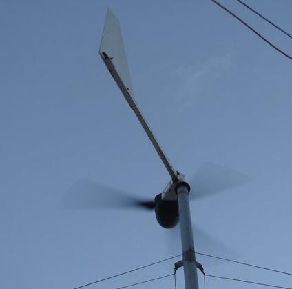
I have got an 2 bladed generator which performed well, but went down in a storm. Everything was o.k. only the prop. was broken. Now I want to build a 3 blade Prop. If I will take the same specs. like width, chord, thickness of the prop. will that be ok. for a threeblader or have I to scale it up . I am new in this forum. Thanks for your help. |
| |
CraziestOzzy

Senior Member

Joined: 11/07/2008
Location: AustraliaPosts: 135 |
| Posted: 05:27am 04 Sep 2008 |
Copy link to clipboard |
Print this post |
|
Not that I currently know a great deal about props...but if your 2-blade design failed in a storm, if you kept the same specs (as queried by you), would you not increase your chance of blade failure in lesser wind events if you increased the design to 3-blade?
A quick picture or mud-map of your prop design would help the prop gurus on this forum answer your question better I think.
http://cr4.globalspec.com/member?u=25757
http://www.instructables.com/member/OzzyRoo/ |
| |
amperius
Newbie
Joined: 04/09/2008
Location: SpainPosts: 7 |
| Posted: 06:30am 04 Sep 2008 |
Copy link to clipboard |
Print this post |
|
hello craziestozzie, thank you for the quick answer,here are the specs. of the broken blade, for the prop gurus!
Radius 1.4 m
Chord width at root 230 mm
chord width at tip 120 mm
drop at root 80 mm
drop at tip 3 mm
tickness at tip 30 mm
many thanks for your help! |
| |
Gill

Senior Member
Joined: 11/11/2006
Location: AustraliaPosts: 669 |
| Posted: 11:35am 04 Sep 2008 |
Copy link to clipboard |
Print this post |
|
G'day amperius,
Perhaps the biggest difference between a 2 bladed prop and a 3 bladed one is in the revs it travels at. A 2 bladed prop has a TSR (Tip Speed Ratio) of around 9, whereas for a 3 bladed prop it's up to 7.
This means a generator will be spun at a faster speed (rpm) for the same wind speed. If you go to a 3 blader, the rpm will be less and this may not suit the generator. To ensure it will have a reasonable performance, the prop specs will need to be remodelled for the slower TSR.
Blade failure is more related to structural integrity than blade profile so it indicates some failure of materials or poor design, like poor quality timber or blade strike of the mast.
I suggest you investigate the cause so as not to have the same thing happen again. I'm thinking this might be a home designed and built mill as redesigning the prop has a large effect on performance. What is your reasoning for the change? What are you hoping to improve and why?
was working fine... til the smoke got out.
Cheers Gill _Cairns, FNQ |
| |
amperius
Newbie
Joined: 04/09/2008
Location: SpainPosts: 7 |
| Posted: 03:30pm 04 Sep 2008 |
Copy link to clipboard |
Print this post |
|
Hello Gil,
the blade failure was not poor material or design, it was because the tower went down in a heavy storm with more then 160 km/h.The reason for this was the poor furling system. I have bought this DIY machine when I knew nothing about windmills. The reason, why I want to change it to a three blader is because I have two "scoraig"mills running I have built by myself, and they work very well with their three blades. I know it�s not the three blades alone, why they work so fine. And a 3 blader is better balanced in wind forces, that is the reason, why I want to change to the three blader, and because now I am very skilled in making them. Another reason is the very heavy make of the two blader that went down, it had 30 mm thickness at the tip! When I have a look at all the 3 bladers like "scoraig" or "Dan B" ones, I will see tips with 4 to 6 mm maximum. That means less weight and fewer forces! But, you are right, I am going to loose RPMs at the same wind speed comparing to the 2 blader. Maybe in the end it needs a bigger Prop and a transmission. This will be more work as a two blade - carving. But if it will be possible to get a lighter Prop with the same performance I would do the job!
Best greetings from
Fritz
|
| |
Gill
Senior Member
Joined: 11/11/2006
Location: AustraliaPosts: 669 |
| Posted: 03:44am 05 Sep 2008 |
Copy link to clipboard |
Print this post |
|
Fritz,
30mm is much to thick for the tip of a 2 bladed prop. With the failing of the furling system I would question all the design aspects. Without pages and pages of report with pictures, it's to hard to suggest what is best to recommend. So let's not go down that road.
I think use your gut instinct on this one. You have a feel for it having watched it perform. You have experience from making 2 Scoraig mills, add to that research where needed and 'use the force Luke'.
As a suggestion, why not find a prop design software and model your new prop with that. If the old prop produced satisfactory gen output, why not enter it's details and work back to what the prerequisites may have been then work forward again but for a 3 blader? I've never done that. It's just an approach I'd try myself if it were me.
was working fine... til the smoke got out.
Cheers Gill _Cairns, FNQ |
| |
amperius
Newbie
Joined: 04/09/2008
Location: SpainPosts: 7 |
| Posted: 01:14pm 06 Sep 2008 |
Copy link to clipboard |
Print this post |
|
Hi Gill,
well, my "guts instincts" combined with "informed guessing" (blade calculators, books and booklets, etc. incl. otherpower etc. ) left me with a stalling windmill.
O.K. here is the rest of the story: After the 2 blader came down, I actually have already converted it into a 3 - blader! I changed the furling system and other things like offset, that did not work perfectly in the old mill.
For the blades I took the same diameter as the 2 - blader had had and used a Scoraigh blade design, scaled to 2,8 meter diameter. Data blades 3 blader : radius 1.4 meter,chord width at root 190 mm drop 40 mm.
Data blade 2 blader : radius 1.4 m , width at root 230mm
drop 80 mm , width at tip 130 mm thickness at tip 30 mm
Generator: Open voltage 650 RPM :190 Volts,
3 phase , motor conversion with PMG,
Ohm: measured from one of the 3 wires to another 2,7 OHMS,
now: with winds 5 to 10 m/sec. RPM 60 - 100 with 1 - 2 Amps at 24 Volt (battery bank).
And that ould have been a happy ending of the story,if the mill did not stall. I think, all the other aspects of the mill are o.k. (when i switch the machine off and let it run free for am moment and switch back to load, the amperemeter rises to 10 and more amps, depending on the winds). The only problem, i think, is to match the prop to the generator. So my only (stupid) question is: which design and which length of the blades are the right ones for my generator?Do I have to go back to a 2 blader, like I had? or would a three blader need a transmission?
Many thanks and best wishes from Espana ! |
| |
Gill
Senior Member
Joined: 11/11/2006
Location: AustraliaPosts: 669 |
| Posted: 02:28pm 06 Sep 2008 |
Copy link to clipboard |
Print this post |
|
I think before you go remaking blades, why not try adding some resistance to the line?
I've have no experience in this regard so best to check your other forum for the recommended resistors value.
I understand the extra resistance reduces the generator loading which allows the gen to spin up past stall.
I find it difficult to see a stall though. There is more torque in 3 blades then two of the same swept area so I can't see excessive loading that causes stall as the problem. I feel it is more likely to be a lack of speed. This could be got by shortening the blades to get the speed up.
Try resistors first as the cost is minimal with no modification of blades. Then if that doesn't work (and I suspect it won't) it's not stalled, so then reduce the diameter to pick up more speed.
What do you(and others) think?
was working fine... til the smoke got out.
Cheers Gill _Cairns, FNQ |
| |
amperius
Newbie
Joined: 04/09/2008
Location: SpainPosts: 7 |
| Posted: 03:47pm 06 Sep 2008 |
Copy link to clipboard |
Print this post |
|
Hi,
Sounds to me like a dejavue. In every forum I have so far tried to get an answer to my question, The discussion went like this one here and in the end as a last straw: try it with resistors.
Sorry, I do not know much about electricity, so I ask you, is it a) a hairdryer b) an water heater c)an opposite politician or d)some glowing windings of any unknown wire material and diameter?
I think I give up! there is no answer in
a) Old Europe b) USA c) Great Britain d) Australia .(was my last hope)
I should ask the man in the moon I think, but as there is no wind,. he neither is the right adress.
Do not take this personally, but there is much more in a windmill I would ever have dreamt of!
Thanks anyway
Greetings from Fritz
|
| |
GWatPE
Senior Member
Joined: 01/09/2006
Location: AustraliaPosts: 2127 |
| Posted: 01:13am 07 Sep 2008 |
Copy link to clipboard |
Print this post |
|
Hi Fritz,
The blades you have made are not identical in profile to the originals. Were you not able to recover enough of the originals to build a copy?
The original blades had a larger root chord and more blade angle. the old blades had much more area as well.
The open cct 190V at 650RPM and the system voltage you have of 24V nom indicate that your working system had around 210RPM at max power. This is not a high RPM machine, so the blades were not high TSR.
The blades you have made are stalling. Adding resistance to the wiring may help. I am not a great fan of this solution.
I think the new blades don't develop enough torque, to get going.
Making wooden blades by hand is almost an art. I have known many men experienced at carving wood in the boat industry make blades that looked good but did not work either.
It would be of use to post a picture of a blade from several angles, eg tip to root from the end view.
Was the person who made the original blades unable to supply others? The fibreglass blades used on a 1kW chinese mill sound similar to what you are after. You may need to make more blades!
Gordon.
become more energy aware |
| |
oztules

Guru

Joined: 26/07/2007
Location: AustraliaPosts: 1686 |
| Posted: 02:20am 07 Sep 2008 |
Copy link to clipboard |
Print this post |
|
The resistance is placed in between the rectifier and the battery. They look like this: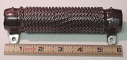
Perhaps start with 1 ohm and see what the difference is.
A good source of these is old forklifts, or old floor scrubbing machines. Usually about .8ohm per resistor for these machines. Older forklifts (before Pulse width modulation speed control) used these as speed control devices and are high power.
You can calculate the wattage of the required resistor by knowing how many amps it has to carry 10-20 perhaps.
The voltage drop is calculated by
volts = current x resistance. gives the voltage dropped over the resistance.
The required wattage of the resistor is:
Watts = current x volts (dropped over the resistor)
Is this what you wanted to know?
..........oztules
Village idiot...or... just another hack out of his depth |
| |
amperius
Newbie
Joined: 04/09/2008
Location: SpainPosts: 7 |
| Posted: 08:14am 07 Sep 2008 |
Copy link to clipboard |
Print this post |
|
hello all,
thank you very much for your answers,
now I understand, that the main mistake making the new blades was not to think about the bigger drop at the root of the old blades and the lager blade area.So the new blades are missing the needed torque. My thinking was: the faster the better. If there is no other chance to improve the performance I will put the genny down and change the blades.
What I will do next is to try the resistors. But, where to buy and what are the specs. Is it ok to ask for a resistor 24 Volt / 1 Ohm or do I need other specs. too. If I do not find any, is it possible to make one by myself,I could make a larger spool, tapping at different contacts for different ohms. but than I must know the wire diameter, wire material, und number of turns. Could this be a way ? |
| |
oztules
Guru
Joined: 26/07/2007
Location: AustraliaPosts: 1686 |
| Posted: 09:07am 07 Sep 2008 |
Copy link to clipboard |
Print this post |
|
In this case, voltage is of no importance. The wattage is.
Before you modify the blades, try using differing resistances to test the characteristics. You can make your own resistors by using all kinds of poor conducting devices. Fencing wire of some length, or I have even used 1mm thick wire springs to tame dc motors.
In some battery chargers I built using low leakage windings (not good for battery chargers), I used 100mm long by 1mm wire springs and stretched them to give some flexability (read resistance)to the low leakage in order to relieve the transformer from low state of charge of flat batteries. (too higher current at start of charge)
You can use heavy secondaries of power transformers in series ... just to get an idea of how the stall changes, then figure out a permanent arrangement later. Once this identifies the problem of stall, you can (by this stage of experiment) create your own resister of suitable power. (it may end up being a few springs in series on a ceramic plate... who knows what you will come up with).
But, before blade carving, try different resistance in series with the dc line, it may save a carving session.
........oztules
Village idiot...or... just another hack out of his depth |
| |
amperius
Newbie
Joined: 04/09/2008
Location: SpainPosts: 7 |
| Posted: 04:45pm 07 Sep 2008 |
Copy link to clipboard |
Print this post |
|
hello everybody,
first of all: many thank for your help, it is a good start for solution!
I tried out to make some"jungle" resistors by myself.It is really "campo - electric". After some trial and errors with different length and diameters of fence wire I found my wifes allround garden wire , I took only 20 cm,so it was no problem. It was 1 mm thick l(thin) I scraped off the coat and made a spool or spring 2.5 cm in diameter and connected it between rectifier and battery. Than I had a look at the amp-meter. I could read more than twice amps than before. The wire got a little bit warm, but not hot...maybe 45 - 50 deg. Celsius. Then I went close to the windmill and measured 8 - 10 m sec. wind, the amp. meter showed 5 - 7 amps. This is much better than before, I remember with the old blade I had 15 - 20 mps in strong winds like 15 - 20 m sec. This evokes some new stupid questions. If the mill produces more watts , will the wire eventually blow? What can I do against this risc with the following runaway failure of the prop and generator?
Many, many thanks for your advices and help!! |
| |
oztules
Guru
Joined: 26/07/2007
Location: AustraliaPosts: 1686 |
| Posted: 11:01am 08 Sep 2008 |
Copy link to clipboard |
Print this post |
|
At 20A, your gennie is absorbing 1000watts of power in it's windings. (20Ax2.7r=54volts dropped in the windings, 54vx20A= over 1000w)
At this time power into the batteries will be 29v x 20A =600watts
So the piece of wire is probably absorbing the least of anyone in the neighbourhood. Burn out of the garden wire is improbable.
However, measure the voltage across the length of the wire while it is passing 10A. I expect it to be around a volt or so. Multiply the measured voltage drop x amps = watts absorbed by the wire. This will give you the wattage of the "resistor" that you have built. I expect a max of 20watts, which if true will not cause much heartburn to the wire.
If still concerned, then use two pieces or wire twice the length of the ideal, and put them in parallel to share the burden If it was 20cm (which seems very little) then use 2 lengths of 40cm side by side. This will halve the wattage seen by each..... or use 4 of 4 times the original optimum length etc. etc.
...........oztules
Village idiot...or... just another hack out of his depth |
| |
