Notice. New forum software under development. It's going to miss a few functions and look a bit ugly for a while, but I'm working on it full time now as the old forum was too unstable. Couple days, all good. If you notice any issues, please contact me.
Dinges Senior Member Joined: 04/01/2008 Location: AlbaniaPosts: 510
Posted: 02:52pm 04 Oct 2008
Copy link to clipboard
Print this post
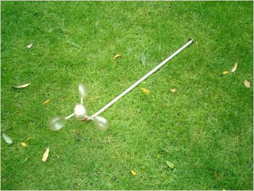
Just another anemometer project. Nothing fancy, but made entirely with scrounged parts.
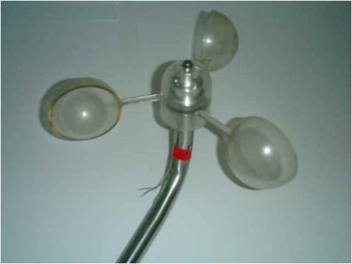
The anemometer vane was bought 2nd hand a long time (~15 years ?) ago at a boat market. Don't think it cost me more than 1 guilder (0.50US$) at the time, brand 'Vetus'. Rather than trying to build something like the vane yourself I'd advise to buy it at a boating supplier, as it's a regular replacement item for anemometers (on boats pieces of rigging tend to quickly damage those fragile vanes).
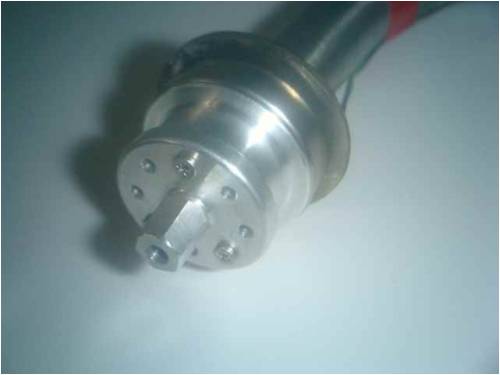
The motor is an old harddisk (HD) motor, 3-phase output, about 1Vac maximum at the normal anemometer speed range. The motor is installed in a piece of bent stainless steel pipe on a welded-on flange. The flange prevents too much rainwater 'creeping up' into the motor. Time will tell if this is enough moisture protection. The output is sent over 3 wires (yet to be installed; it has been tested, but still needs to be 'finished up') to a 3-phase rectifier made of germanium-diodes. I initially tried using just single phase rectification but the rectified AC is just to bumpy at these low frequencies, with the needle of the meter vibrating a lot. The 3-phase rectification solved that.
I made an aluminium adapter to attach the rotor vane to the HDD motor, filing a 6-sided outer-hex 'nut' to fit inside the vane. The adapter is attached to the motor using 3 stainless steel screws.
Still have to install the cable inside the steel arm and calibrate an analog meter (that way no external power supply is needed; the anemometer provides the power it needs for its own readout), but apart from that it's finished. Made entirely from scrap. And, another use for old PC parts... after the PSU, now the HDD motor can be put to good use too. Maybe it's time for a new 'scrapheap challenge': build a windturbine out of old PC parts...
I'll admit it's nothing too fancy and it can't log (I'll leave the logging to the lumberjacks... Hi Oztules!), but for my purposes plenty good enough. There's really no excuse anymore for anyone not having an anemometer. (the HDD motor idea was stolen from the Dans, but I like my model of motor much better than the thick, flat motors they used; the rotor vane now actually acts as weather-protection house for the small motor as well.)
Hopefully the above is of any use to others too.
Peter.
Gill Senior Member Joined: 11/11/2006 Location: AustraliaPosts: 669
Posted: 02:46am 05 Oct 2008
Copy link to clipboard
Print this post
Good one Peter,
I like the idea of the anemometer providing its own power. I'm building another using old HDD motor and I've found there are quit a variety out there. I've found 6 magnetic pole, 8 pole and 12 pole and I haven't even started on the pile under the bench yet. I like the ones with the more poles best though they seem to use a smaller diameter which gives me less room for my hall effect sensor and iron block.
I must check out our local chandlers for those cup heads. Very neat and that'd save me a good bit of work if the price is right.
Out of curiosity, what's the voltage output range and is there a display circuit or a simple labelled millivoltmeter?
Nice project. Well done. was working fine... til the smoke got out.
Cheers Gill _Cairns, FNQ
Don B Senior Member Joined: 27/09/2008 Location: AustraliaPosts: 190
Posted: 10:15pm 04 Feb 2009
Copy link to clipboard
Print this post
Hi Gill
Some years ago I made my own cup type anemometer head using three Andronicus coffee spoons (they came in the tin). It lasted for a long time, but the cups ultimately failed due to UV degradation which, I suspect, might also be the ultimate fate of Peter's aenemometer head (which looks to be clear plastic and thus even more susceptible).
Unloaded cup type aenemometers have a rotational speed that follows the wind speed in a very linear fashion, however, I suspect that any sort of loading (such as self generating a voltage output) will affect the linearity.
In my case, I initially used a car distributor type Hall effect scanner, but the magnetic field as the vane pased through the gap produced drag that seriously affected linearity. I finally used optical scanning with a LED and photo transistor to overcome this problem.
No doubt you could build a big enough head so that a small loading would have minimal effect on the linearity, but it is something to consider.
Don B
Dinges Senior Member Joined: 04/01/2008 Location: AlbaniaPosts: 510
Posted: 07:51am 05 Feb 2009
Copy link to clipboard
Print this post
Don,
You're right about the degradation under the influence of UV light and the weather. I bought the anemometer vane used at a boating show for peanuts and it shows some sign of wear from previous use. The good thing is that it is a standard replacement item from Vetus/Den Ouden (yachting supplier) so should be easy to replace when the need arrives.
The non-linearity is indeed there. In fact, the original Vetus anemometers are very non-linear too, compensating for it by a specially calibrated analog readout. I still have to build an (analog) readout unit for it, but I intend to make a custom scale for it. As long as the scale is correctly calibrated I don't really care much for the non-linearity: my major requirement is that the entire windmeter must work stand-alone, without need for external power. In essence, this anemometer is a VAWT that generates its own power for the readout display. Any kind of Hall-effect sensor or light-bridge would need an external power supply.
Peter.
Don B Senior Member Joined: 27/09/2008 Location: AustraliaPosts: 190
Posted: 10:03pm 05 Feb 2009
Copy link to clipboard
Print this post
Hi Peter,
I suppose that, with an analogue micro Amp meter, and suitably selected series resistor, you could set up a usable self powered anemometer. The complication is how to calibrate it, unless you happen to have access to a wind tunnel (and a helpful operator).
I have heard of people mounting them above their car and calibrating them against the speedo on a calm day (or maybe making runs in opposite directions to compensate for wind drift). The concern for me with this method is that, unless the unit is well clear of the car, it could be in air that has been accelerated or disturbed by the car's slipstream.
As an added complication, I have noticed that, on two cars that I have checked, the car speedo seems to under-read by a significant percentage when compared with the speed read-out on my GPS, which I assume to be more accurate.
Unfortunately also, trying to calibrate against another anemometer runs into the problem of never being sure (except in a general way) that both are simultaneously exposed to wind at the same speed.
You indicate that your anemometer outputs about 1 Volt AC at reasonable rotation speeds. If you need a full wave bridge rectifier for the 3 phase output then, even with germanium diodes, you are looking at a forward voltage drop of around 0.3V per diode. This is going to gobble up a lot of your AC output, and will probably not permit any reading until a certain minimum wind speed is reached. Maybe you could improve this by using only 1/2 wave rectification and a bigger smoothing capacitor??
I guess that it all depends on the accuracy and range that you are prepared to settle for.
RegardsDon B
Jarbar Senior Member Joined: 03/02/2008 Location: AustraliaPosts: 225
Posted: 05:38am 06 Feb 2009
Copy link to clipboard
Print this post
Hello all,
some time ago a post about measuring wind speed using some type of transducer that normally was used for another purpose.I can't remember what it was called.I imagined it could be mounted on a probe the projected in front of the mill say a meter or two and sensing pressure could be used in a feed back loop to control the load on the mill relative to wind speed/pressure.Anyway just another loopy idea for someone to run with.
Well done with your unit Peter.Proficiate!!!
Anthony."Creativity is detirmined by the way you hold your tounge".My Father
"Your generation will have to correct the problems made by mine".My Grandfather.
Tinker Guru Joined: 07/11/2007 Location: AustraliaPosts: 1904
Posted: 12:16pm 06 Feb 2009
Copy link to clipboard
Print this post
Just out of curiosity, while you guys are experimenting with AC producing HD motors, what is wrong using a miniature DC motor. I have one here, quite tiny, with a 2mm shaft and connected it to an analogue multimeter set to DC 3V scale. Spinning the shaft by hand produced a healthy voltage up to almost 2V with a decent spin. Very slow spinning also produced enough to get the meter needle moving.
This would fit Peter's requirement of being self powered and it needs NO rectification at all.
TinkerKlaus
KiwiJohn Guru Joined: 01/12/2005 Location: New ZealandPosts: 691
Posted: 08:01pm 06 Feb 2009
Copy link to clipboard
Print this post
A simple anemometer for a windmill (which of course is always facing the wind) is a horizontally hinged vane connected to a potentiometer and a low voltage circuit to drive a meter.
Tinker Guru Joined: 07/11/2007 Location: AustraliaPosts: 1904
Posted: 01:38pm 07 Feb 2009
Copy link to clipboard
Print this post
Or is it? What happens if the mill furls, its no longer pointing into the wind and an attached vane would read the wrong wind speed.
Me thinks a rotary anemometer is better, mounted above and slightly forward of the main blades to receive clean air.Klaus
KiwiJohn Guru Joined: 01/12/2005 Location: New ZealandPosts: 691