Notice. New forum software under development. It's going to miss a few functions and look a bit ugly for a while, but I'm working on it full time now as the old forum was too unstable. Couple days, all good. If you notice any issues, please contact me.
oztules Guru Joined: 26/07/2007 Location: AustraliaPosts: 1686
Posted: 12:07pm 11 Nov 2008
Copy link to clipboard
Print this post
Well it has been a bit quiet of late, and I have had time to ponder what to do with my new found power source... yes the windmill.
To economically take advantage of the power, I needed to use it to best effect to get the power bill down.
This is easily done with a grid connect converter.... except they are expensive, and an electrician is required to install then .... and there are none on the island at this stage. The last one left some months ago..... plus I felt that it was a bit premature to consider the outlay until I had a good idea of just what we could produce reliably and on a regular basis.
The hot water bill is around 4-6kwh a day I suspect, and so if I could somehow replace this quotient with wind power, it would be a small step in reducing the grid requirements.... a modest start, but a start anyway. At 20c/kwh, it is a dollar a day.... grid power is damn cheap for the energy you get for 20c.
So... I had procured a small (50 liter) electric hot water unit with a still working element... whoppee... now what??
48 volts does not do much into a 240v element I=E/R. It is a 2kw element so W=ExI E=240 so I=8.3A .... R=240/8.3=28ohms So if the element is 28 ohms ExE/R= 48X48/28 = 82 watts at 48v...... not very impressive.... we need a plan B
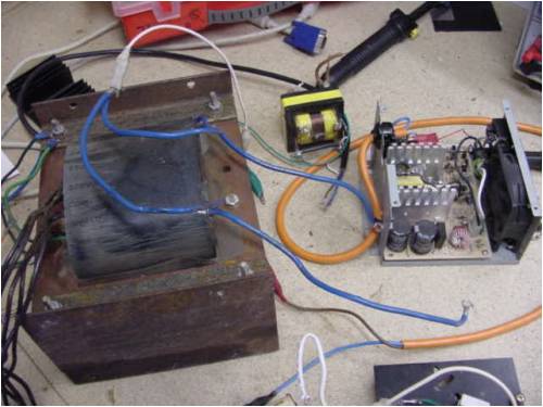
PLAN B:..... looks like this actually
It is a cheap nasty but very effective 800W 240vac 50hz inverter. It eventually became 2kw by using a bunch (8 50A 120v 350W MJ11033): darlingtons and this monster 40lbs transformer:
I had it running nicely with this setup, until I dropped a screwdriver onto the rails of the transistors... killing one, and it managed to take out the other 7 at the same time.... 30 dollars of transistors out the window.... sigh clumsy clumsy oaf
So Plan B went to hell in a wheelbarrow... I'd run out of bipolar victims for the time being (I had a heap of 2sk1609 fets but at 900v the rds on was too high... even if I used 20 of em...curses), so it was on to a simpler PLAN C.
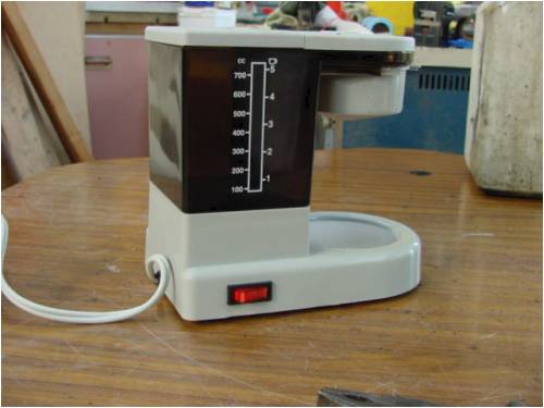
PLAN C consisted of rattling around in the shed for that car coffee maker I had purchased years earlier, and felt was useless.... but had kept it anyway. It had cost a princely 5 dollars, and for how it worked ... it was overpriced.
However... I had plans for it right now.... were going low tech this time.
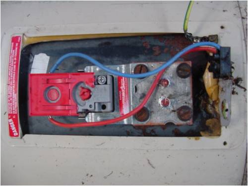
It looks like this in it's native form:
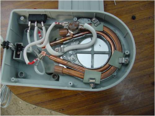
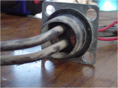
I know it doesn't look much, but look in here:
With some gentle persuasion, you get the good bits out like this:
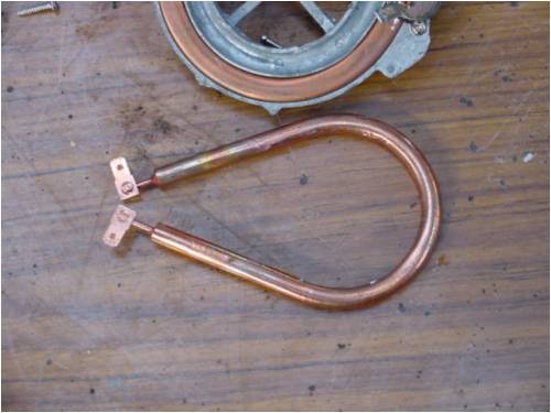
Here is a picture of the original element, with the new kid in town next to it and bent to shape.
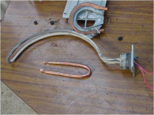
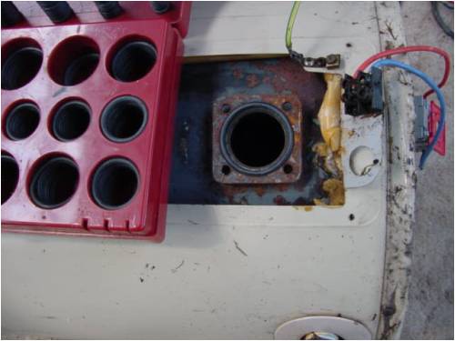
And a picture of what we need it to fit into/look like:
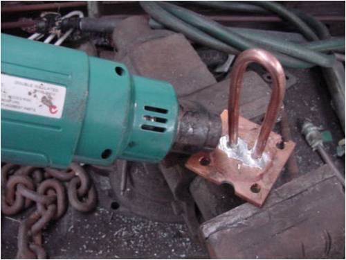
Ok now we need to cut out a piece of copper plate (1/4"thick mine was 65mm square with the outer 4 holes at 45mm centers), with the two holes in the middle area to accommodate the coil legs to come through.
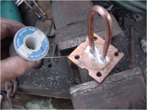
Now we just need to solder the legs into the copper plate. Clean the copper plate with some sand paper, likewise the coil jacket.
I don't have a torch, so I use a hot air gun to heat up the copper, like this:
And then run the solder into it like this:
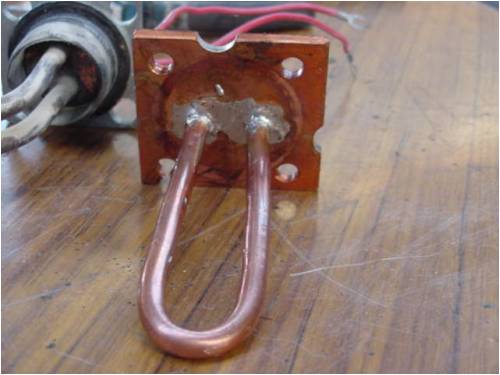
And we are rewarded with this:
Now we screw it into the water heater and were good to go. The temperature control is integral with the fitting, and we will use that as well. An O ring is used to seal the plate to the housing like this:
Finished it looks like this:
So it is off to the hose to half fill the tank and check for leaks. As it fills, I close off the outlet with my finger and let the air pressure insdie build up against the water pressure so I can test for leaks.... there are none..... wonder where Murphy is hiding today....
Well, we have a water tight water heater set up for 12vdc@120watts.... not good enough I say.
With some seat of the pants dead reckoning (otherwise known as a blind guess) I figured this thing was good for 500watts at least and for short periods probably 800 watts. There is only one way to find out.... plug it in.
On 12v it drew 10 amps, on 24v it drew 25 amps. 36 was out of the question and 48 was looking for an explosion of some sort..... already had that with the transistors so didn't want another one.
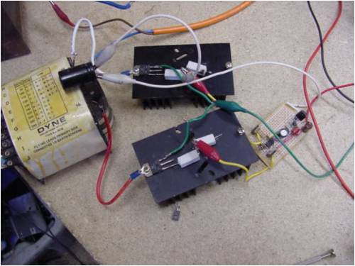
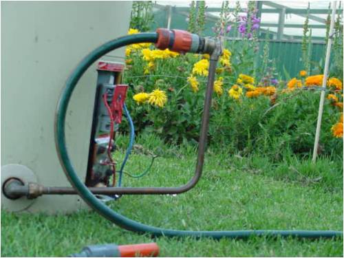
I had a DC motor controller I had built for a motor ( to grid drive a 10hp induction motor...... to watch the meter fly backwards... idle curiosity), and this looked like a good time to wheel it out.
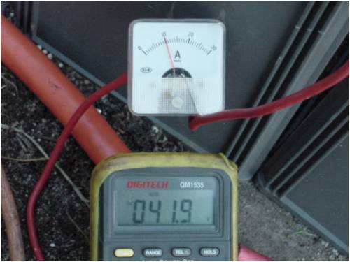
So, driving with 42v into the controller, I dialled up 10 amps on the input amp meter so I was drawing 400 watts or so. like this:
I had an amp meter on the output and measured the voltage into the heater... it looked like this:
In my language, thats about 100 watts.... methinks Murphy has arrived and stolen the other 300 watts.
This is obviously some cause for some concern... 400 in, 100 out..... not good. I wound the control pot on the motor controller up to 25A@40v...... were talking about 1kw here. I could hear the element boiling the water in contact with it.....but the meter on the input said 25A@21v...only 500w or so, but the wire was hot... there was lots more than 500w going into it.
I backed it off to 7A input@42v... 280watts is plenty enough to do what I want..... but what happened to the other 4-500 watts.
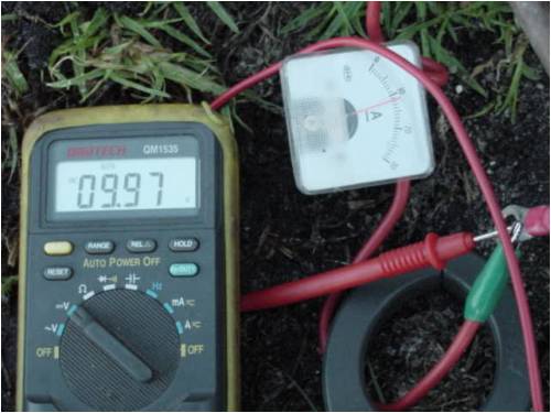
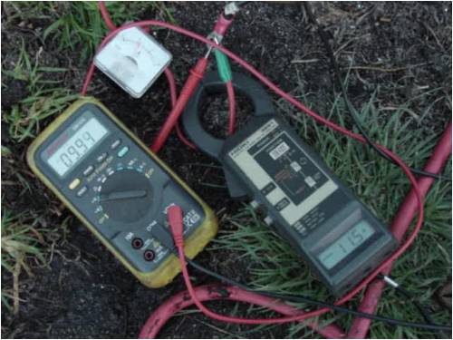
I had an AC clamp current meter. I put that on the dc line to the water heater... and there it was... my extra power was in AC form.
So the mystery was solved, because the motor controller was chopping the power, the current was going to the element measured as 11.5A on the ac current meter, 10 or so amps on the DC meter, 10vdc on the dc volt meter, and 17vac on the ac meter... funnily enough it roughly adds up to the input power. The chopping also caused a small deviation on the input readings, but not enough to take any notice of. If I had been only taking the output readings, I would have blown the element in a fairly short period of time.... just beat Murphy this time.
So there you have it, a quick (about an hour or so) conversion from coffee maker to water heater for virtually no cost, and a chopper to drive it. It would run nicely straight off 18v ...24v will be a bit heavy I think...(about 5-600w.... not sure how long the element would last as it would draw about 25A at that voltage. The good thing about the chopper is that it gives you total control of current draw, and you can use the dead time control to turn it on and off from the thermistat at milliamps, not amps.
............oztulesVillage idiot...or... just another hack out of his depth
Dinges Senior Member Joined: 04/01/2008 Location: AlbaniaPosts: 510
Posted: 05:08pm 11 Nov 2008
Copy link to clipboard
Print this post
Nice project!
Mine's about 3kWh (Dutch bathing habits are not unlike those of pommies... best place to hide something is under a bar of soap ), about half of daily electricity use (6 kWh/day total nowadays; 3kWh of which for heating water). It's the single-most powerhungry appliance I use now.
Funny, I've toyed with that idea too (I toy with a lot of ideas... very few get actually carried out )... use 12V heating element (either a 'cup water heater' thingy or old 12V coffee maker). Good to see you got it working. Downside of the low voltage is the need for thick wires...
300W isn't a lot (my electric water heater is 3600W, IIRC), it heats a 50l tank and runs a little under one hour per night. If your 12V thingy would work 24/7, then it'd produce about the same energy. Not bad!
My main worries:
1) the heater isn't designed to run 24/7 (let alone be pushed beyond its limits); may severely limit its lifespan.
2) the soldering. I'd definitely have brazed (silver-soldered) the heater to the mounting plate; using plain electronics solder (eutectic 60/40) melts at 183 deg. C and looses a lot of strength below that temperature. I know boiling water (at sea-level) can't get above 100 deg. C... but still. Too little margin, me thinks. Then again, it's also used here for soldering water pipes... so it may be mechanically sound too ? Dunno, I maintain I'd have brazed it. Stronger and can withstand much higher temperatures.
And your point is... ?
Go out and buy one man. Geeze. How can you live without one ?! (Peter counts his torches... 2 in the main (electronics) toolcase; one in the other toolcase; one in the tooldrawer in the shop; 2 larger blowtorches with 2 or 3 L propane tanks in the shop... In other words: a torch - don't be caught without one!). And you claim to have none ? I feel sorry you; poor bastard.
BTW, I like the way you use alligator clips to connect the inverter. Looks much too familiar to me . Keep in mind that those cheap and nasty wires/clips (ever opened one ? More plastic insulation than copper wire in them) have large resistances, ~0.5-1 ohm. I consider them 'connectable fuses'. The best part: they start to smoke before they open, thus giving a warning. I normally put a 2nd wire parallel over the ones that smoke . And I permanently have 4-5 wires that are waiting for repair (I replace the cheap wire by much thicker, usually taken from old PC PSUs (hey! Another use for those PSUs!).
Anyway, very nice project.
Peter.
Edit: in hindsight I'm surprized you haven't built & installed a solar water heater yet. In Australian climate... Now *that* would take the major cost out of the electricity bill. Anyway, a batch heater is high up on my priority list of things to build.Edited by Dinges 2008-11-13
philb Regular Member Joined: 05/07/2008 Location: United StatesPosts: 96
Posted: 08:10pm 11 Nov 2008
Copy link to clipboard
Print this post
I ran aground while trying to create dump loads for hot water tanks. My old and now gone 12 volt system used a 'cup of water thingy' that worked quite well for about a month. It went ZZZZTTT at the wrong time, causing overcharged batteries. No obvious exterior damage. Frustrating...
The solution for my 48 volt system:
Step up to a suitable voltage, rectify, combine phases and power the original element with DC. Not perfect, but usable. philb
oztules Guru Joined: 26/07/2007 Location: AustraliaPosts: 1686
Posted: 09:39pm 11 Nov 2008
Copy link to clipboard
Print this post
Not really, it is only drawing 7A at 42+ volts, so not excessive. The chopper makes it quite versatile. I will upgrade the fets so I feel comfy with the chopper running at 48-55v. It would be pushing the BUK556's a bit close for comfort at 55V and beyond.
The solder will be fine, as the max temp the copper plate will see is 65 degrees C.... A big water cooled copper plate heatsink.
I have found that the heat gun is a brilliant device, and doesn't run out when you least expect it. Gettting gas over here is problematic. You cant's freight the tiny gas bottles by post or plane... 45kg bottles are a bit large to work with..... and there's no beans in the garden.
Islands can present problems sometimes. My MIG has run out of gas.... none on the island till next shipment from Victoria.... when ever that is.... so I rewired the internals of the MIG to run as a conventional DC welder (up to 215A) and can weld with fencing wire to welding rods now..... but still waiting for the gas.
Yes... the alligator clips. Too too handy those things. I have very few left with the original wire. If you check out the amp meters above, they have the same clips... but 6mm 50A wire going to them. Most get replaced with the innards of 15A extension cord wire. Those little clips can stand upwards of 45A for a short time I have found.
When I was driving the hot water unit from the slapped together inverter, it was pulling 43A@50v..... through alligator clips.... from batteries to emitters, from collectors to transformer etc....The original size drove the darlington bases..... I guess I'm still just a vandal at heart.
Solar..... yes funny you should mention that. I am helping a fellow pull out some windows on his house next Monday. Now on an island, that usually means someone else will put them in their house.... but this time I have gottem.... and it will be for a solar water heater... stay tuned
Philb,
I have no idea how well the heating element is made. Some will be good , some poor. It is only nichrome wire encased in a ceramic powdery material..(from the looks of it) inside a copper pipe/jacket. If not pushed to melting point for the nichrome, it should have a reasonable life span.... time will tell if I am pushing it too far. It only takes a few minutes to replace it with another...(4 bolts and a heat gun) emptying the water will take the longest.
...........oztules
Edited by oztules 2008-11-13Village idiot...or... just another hack out of his depth
Dinges Senior Member Joined: 04/01/2008 Location: AlbaniaPosts: 510
Posted: 10:28pm 11 Nov 2008
Copy link to clipboard
Print this post
I should have expressed myself more clearly, I was more thinking about the way I was planning on solving the problem, with a 12V heater (i.e. a 12V system), not commenting on your system. I suppose the 42V input isn't an issue, as long as you limit current as you do. Little risk of burning out the heater because of overvoltage, I think, unless the 42V would be too much for the heater insulation (which I strongly doubt). That's ignoring the fact that you grossly overload the heater, 280W vs. rated 120W.
Correct, I forgot that you don't want boiling hot water in a boiler, just 65-75 deg. C warm water. That gives a bit more margin for the solder. But, if you're using that water heater as a dumpload, you should take into account that the water temperature could rise up to 100 deg.C; or have you wired the heater element to the (original) boiler thermostat? If so, then you'd need a secondary dumpload to protect the windmill, to kick in when the primary dumpload (the water heater) cuts out.
Slightly surprized by this, as a MIG welding machine has a constant-voltage source characteristic, whereas a stick (and TIG) machine has constant-current characteristic. So, it makes me wonder a bit how your welds look like, if you use a MIG machine for stick welding...
Edit: on closer reading... maybe I misunderstood, but if you really use fence wire as welding filler/electrode... then ignore the previous paragraph, as the source-characteristic of the welding machine is the *least* of your worries in that case. Oh, and do me a favour .... never, *ever* post a picture of your welds here. Or at least post a clear warning in the thread title so I can skip the story.
Have you considered flux-core wire for the MIG ? No need for gas, and much easier to weld with than stick. But considering that you can buy a stick welder here for 35E (yes...) and an inverter welding machine for 135E... And considering how easy it is to build a stick welder using a large transformer, I'm surprized you haven't built one yet
Definitely looking forward to your story on the solar water heater, no doubt with an original Oztules' touch . What configuration are you thinking of, a batch heater or solar collector panels ?
Edited by Dinges 2008-11-13
GWatPE Senior Member Joined: 01/09/2006 Location: AustraliaPosts: 2127
Posted: 10:46pm 11 Nov 2008
Copy link to clipboard
Print this post
Hi oztules,
If you are drawing 7A @ 42V. This is probably measured as RMS. The square wave chopper has probably 33% duty I imagine. This translates to 21A pulses for 33% of the time to give the 7A RMS. Some power will be heating up the wiring during those 21A bursts. Factor the 21A into the FET i^2R loss as well.
Gordon.Edited by GWatPE 2008-11-13become more energy aware
oztules Guru Joined: 26/07/2007 Location: AustraliaPosts: 1686
Posted: 11:04pm 11 Nov 2008
Copy link to clipboard
Print this post
Yes Dinges, the therm is wired to the duty cycle of the speed control. So it turns the controller on and off 65 degrees I set for last night. This morning, it is turned off, and awaiting further cooling before turning back on.
It seems that we only really use water (hot) at night, so this thing has all day to warm up from the previous night. It may be that I can turn it back further. It is not used as a dump load..... need more than this to do that by a long way. Testing the furl the other day saw 40A@59v.... I don't think this will have a snowflakes hope in hell of coping with that sort of input. The batts are now 400ah, and hold the voltage down reasonably well.
At this stage, I turn it off when I'm not playing with it or run it stalled... then almost regardless of wind, it puts out 2-4A@27v. even in high winds it only manages 6A so the alt is pretty tight I think. (yes seperately charging a 24v bank.... rehabilitating them from the tip.
The mig can use 5mm thick rods, and eats them up at high settings. The welds are better than with my old stick welder..... but thats no recommendation. Batteries with a choke work well in a pinch.... and without a choke if your desperate.
Flux cored mig .... I have had poor success with the little Italian mig I had with that, so gave the mig away for free, and never bothered to put that wire into the big mig. ... I just wasn't impressed I guess.
...........oztules..... wanders off thinking about building a solar hot water heater.... and realises he knows nothing about it Village idiot...or... just another hack out of his depth
GWatPE Senior Member Joined: 01/09/2006 Location: AustraliaPosts: 2127
Posted: 01:59am 12 Nov 2008
Copy link to clipboard
Print this post
Sorry oztules, I have a comment on welding wire related to your thread.
Hi dinges,
Welding wire? When I was welding up my solar racing car, I used a tig welder. The space frame chassis was made from seam welded chrome plated curtain rod, around 0.8mm wall thickness. I used galvanised 0.6mm soft iron wire as the filler rod. The stuff you use in the garden that is easy to break. I was told by a few engineers that the welds would be weak. All attempts to break the welds, resulted in the main tubing failing. I have to admit that the welds did look pretty good though. You just have to cover up and use a good mask. BTW the flux cored MIG wire produces a lot of smoke that is probably not good for you.
Gordon.
become more energy aware
Dinges Senior Member Joined: 04/01/2008 Location: AlbaniaPosts: 510
Posted: 03:41am 12 Nov 2008
Copy link to clipboard
Print this post
Hi Gordon,
[quote=gordon]
I used galvanised 0.6mm soft iron wire as the filler rod. The stuff you use in the garden that is easy to break.[/quote]
No doubt that works fine with TIG, as you use Argon shielding gas. 'Real' TIG feeder wires are basically mild steel with a small amount of additives (de-oxidizers amongst others, IIRC), but no doubt you can make good welds without them (I have, in fact, done the same as you, but using plain stick electrodes as feeder wire for TIG, after having removed the flux mantle). The only thing I worry about is the galvanization of the wire you used. VERY unhealthy smoke and it won't improve weld quality. I always get a metallic taste in my mouth welding galvanized stuff where I haven't removed enough of the galvanization. Not healthy...
In TIG (and MIG) you have a shielding gas. In stick welding you don't. Now, in the beginning of stickwelding (somewhere around 1895-1905, invented by a mr. Slavianoff, hence initially called the 'Slavianoff method of welding', nowadays known as stick or MTAW) people actually did just that: use plain mild steel electrodes without a flux coating. The welds were lousy by today's standards, mostly because of hydrogen porosity. The welds were very brittle, not ductile. This severely limited the application of the welding process. It wasn't until flux-covered electrodes appeared that this improved and welding could be used for more critical applications where ductility was important, thus replacing riveting.
So, in a *really* desperate situation one might use fence wire to stick weld, but even then I'd never use it for any 'critical' welds, i.e. anything that takes a load, especially dynamic loads. That's just asking for trouble with hydrogen-porous welds (which they WILL be). Using mild-steel wire in TIG (or probably MIG too) works pretty good though, but there we have a shielding gas that prevents (hydrogen) porosity and other contamination of the puddle.
I have a Lincoln SP175-T MIG welder that works perfectly fine with flux core. Yes, it spatters and smokes much more than real MIG (flux core wire behaves more like a flux-covered stick electrode), I dress up as I do for stick when welding and arrange for adequate ventilation. Apart from that it's a plug & play machine. I have no doubt I could teach my mother to weld with it in under an hour.
I suspect the reason Oztules didn't like his Italian small MIG machine is because of wire feeding issues, at least that's a common problem I hear about with cheap DIY-store MIG machines. Haven't had any issues with the Lincoln. For more challenging jobs the ESAB DTD250 AC/DC TIG machine gets used (also for stick). 3-phase inverter, 250A output, AC and DC, watercooled torch. For stick jobs without 3-phase power I have a small transformer stick machine. Cheap & nasty, but does the trick.
But, unlike Oztules, I have no trouble getting welding supplies or shield gas over here...
Peter. (with apologies to Oztules for going off-thread)Edited by Dinges 2008-11-13
dwyer Guru Joined: 19/09/2005 Location: AustraliaPosts: 575
Posted: 10:49am 12 Nov 2008
Copy link to clipboard
Print this post
HI Dinges
For stick jobs without 3-phase power I have a small transformer stick machine,Tigwelder,mig welder320 amp .
Most of stick welder dont run on 3 phase transfomer but they run on single phase 240volts or 415 volt but 2 wire out 3 wire 3 phase and welding galvanizatize coat steel can cause damage to lungs and later in life is cancer in the lung and white smoke is the same nasty stuff is use on fluro light or compact light as 20 years ago l have been welding mig with bronze wire (not steel)on brass sheet metal for QLD Goverment everyday my welding helmet was cover with white power , Anyway the finish brass frames is still at the top of the roof of Parliament house in Brisbane. Any how My mig welder won't run well on my 12 kw 3 phase generater so i use 240 volts inverter DC stick welder connect to mig wire feeder and had 24 volts dc tranfomer to run the wire feed motor and it work fine in welding however the voltage was high around 60 instead 24 volts for most mig welder
Dwyer
oztules Guru Joined: 26/07/2007 Location: AustraliaPosts: 1686
Posted: 08:17pm 12 Nov 2008
Copy link to clipboard
Print this post
.......my kind of animal
......oztulesVillage idiot...or... just another hack out of his depth


 ), about half of daily electricity use (6 kWh/day total nowadays; 3kWh of which for heating water). It's the single-most powerhungry appliance I use now.
 )... use 12V heating element (either a 'cup water heater' thingy or old 12V coffee maker). Good to see you got it working. Downside of the low voltage is the need for thick wires...
 water heater is 3600W, IIRC), it heats a 50l tank and runs a little under one hour per night. If your 12V thingy would work 24/7, then it'd produce about the same energy. Not bad!
 buy one man. Geeze. How can you live without one ?! (Peter counts his torches... 2 in the main (electronics) toolcase; one in the other toolcase; one in the tooldrawer in the shop; 2 larger blowtorches with 2 or 3 L propane tanks in the shop... In other words: a torch - don't be caught without one!). And you claim to have none ? I feel sorry you; poor bastard.
 . Keep in mind that those cheap and nasty wires/clips (ever opened one ? More plastic insulation than copper wire in them) have large resistances, ~0.5-1 ohm. I consider them 'connectable fuses'. The best part: they start to smoke before they open, thus giving a warning. I normally put a 2nd wire parallel over the ones that smoke
  . And I permanently have 4-5 wires that are waiting for repair (I replace the cheap wire by much thicker, usually taken from old PC PSUs (hey! Another use for those PSUs!).


 . What configuration are you thinking of, a batch heater or solar collector panels ?
 and later in life is cancer in the lung and white smoke is the same nasty stuff is use on fluro light or compact light as 20 years ago l have been welding mig with bronze wire (not steel)on brass sheet metal for QLD Goverment everyday my welding helmet was cover with white power