| Author |
Message |
greg199
Newbie

Joined: 03/11/2015
Location: AustraliaPosts: 39 |
| Posted: 12:24pm 14 Oct 2022 |
 Copy link to clipboard Copy link to clipboard |
 Print this post |
|
I have acquired a Seeley variable speed single phase 230V AC motor rated at 750W and 1250 Var RPM that appears in excellent condition. The model number is 5057V4A007, part number 822662.
I'd like to get it working with a variable speed but there was no power supply with it and the wiring diagram sticker in the terminal box is incomplete. The power cord is cut and simply consists of 4 wires : brown, orange, blue, green. The capacitor tests fine (20uF) and coil resistances test fine.
Much internet searching reveals that it is possibly from an Australian Breezair evaporative cooler - but that is far from certain.
Anyway, anyone know where I can source a cheap power supply unit for it so I can play around with it?
(One option is to join the brown and orange wires as active, keep the blue neutral and green earth and plug it into an outlet and see what happens but I'd like to check other options first.)
I plan to call around to see if any aircon technicians have a supply but in the meantime maybe some ideas from here will help. |
| |
phil99

Guru

Joined: 11/02/2018
Location: AustraliaPosts: 3323 |
| Posted: 09:26pm 14 Oct 2022 |
Copy link to clipboard |
Print this post |
|
Your assumption about the brown , blue and green wires is almost certainly correct. The orange wire might be a 240V speed control wire, but it could also be a low voltage control so it might be best not to connect it until you have traced the circuit.
More circuit tracing to work out what voltage the missing power supply should be. I assume it powers a PCB (post photos of both sides and a sketch of where the wires go), check the voltage rating of all electrolytic caps., logic chips, transistors etc. The supply voltage will be less than that.
To determine what type of control signal it needs you will need to trace the whole circuit on the PCB.
Edit
Is this the one?
https://www.gamato.com.au/product/seeley-750w-variable-speed-motor/
This
https://shop.seeleyinternational.com/products/095042
indicates it is just a two speed motor.
In that case the orange wire may go to active to select high speed.
Edited 2022-10-15 07:46 by phil99 |
| |
greg199
Newbie
Joined: 03/11/2015
Location: AustraliaPosts: 39 |
| Posted: 01:06am 15 Oct 2022 |
Copy link to clipboard |
Print this post |
|
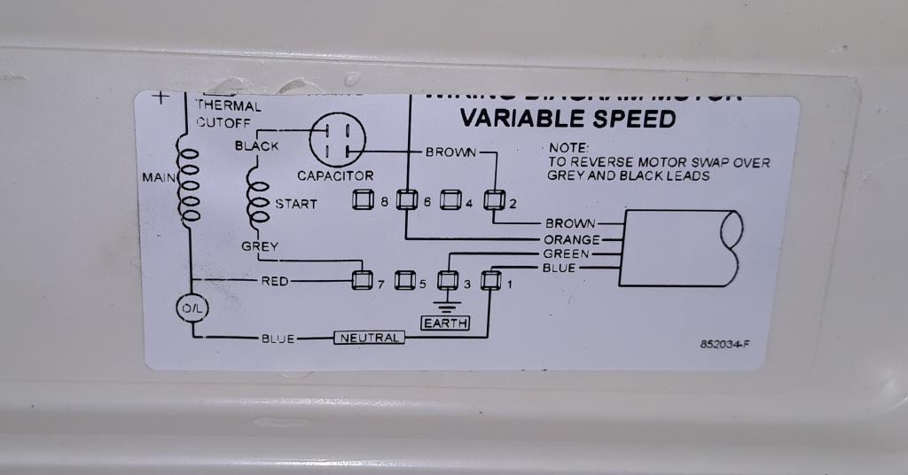
Yes that Gamato link is correct - a variable speed motor. No PCB. Here's the wiring diagram that is inside the terminal box lid. The top section is cut off and when I checked another identical motor its diagram was also incomplete - a printing problem at the manufacturer I guess.
And here's the full specs....
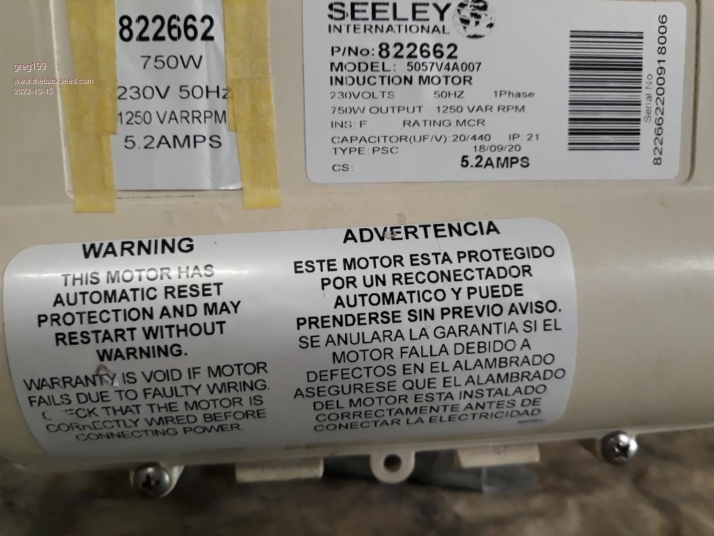
Capacitor is 450VAC 50/60Hz.
Edited 2022-10-15 11:09 by greg199 |
| |
phil99
Guru
Joined: 11/02/2018
Location: AustraliaPosts: 3323 |
| Posted: 12:02pm 15 Oct 2022 |
Copy link to clipboard |
Print this post |
|
There can't be much missing from that wiring diagram. My guess is just the main winding going to the orange wire via the thermal cut-out. You could check that with a multimeter easily enough.
The speed control is probably a triac phase controller connected between active and orange. Essentially a high power light dimmer modified to cope with a highly inductive load.
To run at full speed just connect orange to active. |
| |
greg199
Newbie
Joined: 03/11/2015
Location: AustraliaPosts: 39 |
| Posted: 12:46pm 15 Oct 2022 |
Copy link to clipboard |
Print this post |
|
Thanks for the feedback phil99.
I was going to do two tests tomorrow: one just powering the start winding & capacitor (orange wire not connected) and the second by powering both windings by joining the orange and active brown. From what you're saying that means I can have two speeds.
If so, that is good enough for me.
It seems odd to me to label the start winding as "start" given that it not only starts but runs continuously at a lower speed (with no power through the main winding orange line). Is that just my lack of electrical knowledge? |
| |
phil99
Guru
Joined: 11/02/2018
Location: AustraliaPosts: 3323 |
| Posted: 10:37pm 15 Oct 2022 |
Copy link to clipboard |
Print this post |
|
Just powering the "start" winding won't work, unless you manually spin the shaft to get it started. It is a split phase motor, both windings must be powered. The capacitor provides a leading phase shift to the start winding current, relative to the main winding. This creates the necessary rotating magnetic field to make the rotor spin.
The triac speed control reduces the power available to the main winding, and gives it a lagging phase shift, improving the rotating field.
With this type of speed control the decrease in speed is due to the torque required by the fan, without a load the speed won't change much if at all.
.
Edited 2022-10-16 08:44 by phil99 |
| |
greg199
Newbie
Joined: 03/11/2015
Location: AustraliaPosts: 39 |
| Posted: 12:36am 16 Oct 2022 |
Copy link to clipboard |
Print this post |
|
That all makes sense. Thanks for the explanation.
Any suggestions for where I can buy a triac speed controller for this motor - an Australian supplier (Perth in particular)? |
| |
phil99
Guru
Joined: 11/02/2018
Location: AustraliaPosts: 3323 |
| Posted: 07:30am 16 Oct 2022 |
Copy link to clipboard |
Print this post |
|
I don't see any local ones rated at more than 300W
https://www.aliexpress.com/item/1005003668378320.html
https://www.aliexpress.com/item/32969943678.html
One of these might be suitable, it's hard to tell. The descriptions are rather vague. One says it is a SCR type, which you don't want but a reviewer said it worked well on an AC fan so perhaps it is really a Triac.
If you get one it would be pot luck. To test it plug a heater in to it and see if the output is AC or DC. If DC it is an SCR type and no good.
At least no good for your motor. It would be fine for power tools with universal motors that don't already have a speed control.
Edited 2022-10-16 17:39 by phil99 |
| |
phil99
Guru
Joined: 11/02/2018
Location: AustraliaPosts: 3323 |
| Posted: 12:13pm 16 Oct 2022 |
Copy link to clipboard |
Print this post |
|
Found a suitable light dimmer circuit and adapted it for an inductive load.
Untested.
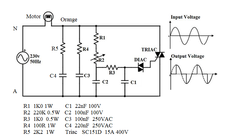 |
| |
greg199
Newbie
Joined: 03/11/2015
Location: AustraliaPosts: 39 |
| Posted: 12:00am 17 Oct 2022 |
Copy link to clipboard |
Print this post |
|
I appreciate the effort you've invested phil99 - even providing a design. Unfortunately I don't yet have the skills or equipment for an electronics build but it will be a good project for me when I've completed all my outstanding tasks.
In the meantime, I'll settle for a single speed.
By the way you were correct.... if I give the shaft a manual start in either direction the start winding will continue to run without the main winding (orange wire) connected. Joining the orange and active wires results in an unassisted start and high single speed. |
| |
phil99
Guru
Joined: 11/02/2018
Location: AustraliaPosts: 3323 |
| Posted: 03:43am 17 Oct 2022 |
Copy link to clipboard |
Print this post |
|
You could get it to work as a two speed motor with a switch from active to orange. Just make sure the switch is closed (high speed) before powering up, then switch to low speed once it is running. |
| |
Godoh
Guru
Joined: 26/09/2020
Location: AustraliaPosts: 680 |
| Posted: 07:24am 18 Oct 2022 |
Copy link to clipboard |
Print this post |
|
Not sure your two speed idea would work Phil. Looks to me that the motor is setup to run with the start winding across the full supply voltage and they are varying the voltage on the main winding to vary the speed.
If you were to try and run it only from the start winding, it would have hardly any torque.
On light loads that may work but usually two speed motors actually have separate windings for the two speeds, eg, a 2 pole winding that is reconfigured to give 4 poles when the connections are changed.
It may work with just the start winding on low power but I would worry that the start winding would burn out.
Pete |
| |
phil99
Guru
Joined: 11/02/2018
Location: AustraliaPosts: 3323 |
| Posted: 11:51am 18 Oct 2022 |
Copy link to clipboard |
Print this post |
|
The motor is designed to drive a fan. The torque required by a fan drops dramatically as the speed is reduced. My guess is that the "start" winding, with it's series capacitor has been designed to provide just enough power for the minimum speed. Greg has already found that it will continue to run, once it has been started, with just the start wining.
As he can't find a suitable speed control that and full speed are the only options.
Simple triac speed controls rely entirely on increasing the amount of "slip" below synchronous speed and thus have very poor speed regulation. It is only a fans predictable torque - speed curve that makes it usable. |
| |
