
|
|
Forum Index : Other Stuff : Generator Wiring Help needed.
| Author | Message | ||||
| Davo99 Guru Joined: 03/06/2019 Location: AustraliaPosts: 1584 |
Just picked up a new generator/ alternator. Bit confused ( lot confused) with it as I have never had a 12 Wire before and the info on the unit seems contradictory. The label on the machine says it's single phase but all the diagrams in the dog box bar a couple are for various 3 phase configs, some of which I have never heard of... not that means much, but seems more complicated than I expected and I don't understand. I'd like to wire it full output single phase. I think it is correct atm but would like to verify. Can anyone tell me in simple terms the wires I have to group together and the connection points? Specs on outside of the machine: 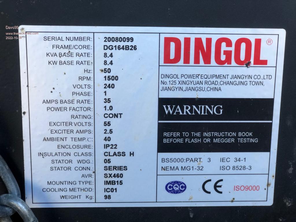 Diagrams under Dog box lid: 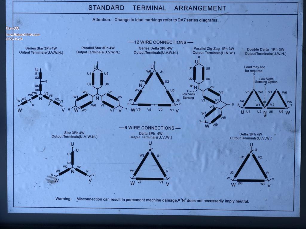 Terminals in dog box: https://www.facebook.com/marketplace/item/232675062383765/ The thing does have an AVR which is connected. I have no idea what the drawn on pos and neg markings are. Previous owner said he had run and tested it but it did not do what he wanted ( although didn't answer when I asked what that was ) and I have not yet connected it to an engine. Looking at where the AVR is it may be in single Phase atm but the marking on the leads are confusing. I have looked up the machine but can't find anything of help on the manufacturers web site. I take it this is a no longer produced model as the one currently listed is a Higher output than this one in the same model. Mine is a 2 bearing model where the ones shown for the same series are single bearing. http://www.dingolpower.com/english/product_list_detail.php?cid=6&id=18 Any help with simple wiring explanations would be greatly appreciated. |
||||
| phil99 Guru Joined: 11/02/2018 Location: AustraliaPosts: 2579 |
Since the nameplate indicates single phase it would have been wired as Parallel Zig-Zag when it left the factory. As long as no alterations have been made it should just work. The stator is 3 phase dual voltage. The Zig-Zag connections create a vector sum of all three for single phase use. Make sure the wire / terminal labels match the diagram and all should be well. Re the AVR, is this a brush or brushless type? If it has brushes + and - might be the AVR output to the rotor. If self excited the polarity needs to match the polarity of the residual magnetism for reliable excitation at startup. Trial & error may be the easiest way to determine that. One way it works, the other it doesn't. As it seems to have a separate exciter rotor polarity won't matter. Alternatively + and - might be the output of the exciter going to the AVR. Trace the wiring and post a diagram, with photos of the guts. Edit Each winding produces 120V so the vector sum in Zig-Zag is:- (120 at 0 deg) + (120 at +60 deg) + (120 at -60 deg) = 240 U and W are active and neutral N is the sensing point for the AVR. Edited 2022-10-28 21:16 by phil99 |
||||
Revlac Guru Joined: 31/12/2016 Location: AustraliaPosts: 1151 |
Should also lookup the sx460 AVR wiring diagram or manual, the wires going to the AVR should have labels or numbers. The cummins stamford alternator I have (23Kva), used the same AVR, but someone messed up the wiring on the rest of it. Cheers Aaron Off The Grid |
||||
| phil99 Guru Joined: 11/02/2018 Location: AustraliaPosts: 2579 |
"Should also lookup the sx460 AVR wiring diagram or manual" Found the manual, it seems this AVR is intended for self excited alternators so residual magnetism polarity will matter. |
||||
| Davo99 Guru Joined: 03/06/2019 Location: AustraliaPosts: 1584 |
Noticed the terminal Block pic link was wrong. 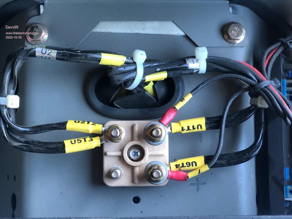 Had another look today while getting one of the diesels that has been sitting round a couple of years running. As I suspected Injector pump had gummed up which wasn't hard to clean but putting the thing back to engage the internal throttle lever took so time and re trys. I think the Alternator may be set up for single phase atm but I will re check the connections and write them down as the codes on the wires are a bit confusing as to what is written on the wiring diagrams. Going by the connections of the AVR as well as the genset itself, I think it may be correct. Next thing will be to get a Pulley for the shaft. I'll get a taper lock probably about 6". Still deciding what engine to put on it as that will also dictate what size pulley I need. I'm leaning to a 30 HP twin Cyl air cooled Ruggerini I have which I could probably drive 1:1 which would help keep the noise down. Not my first preference for an engine but what I have and engines seem to have all but dried up in the used market. It needs a plate with a shaft to bolt to the flywheel and I think getting one could be fun and I'm not sure if the bolt spacing is standard on stationary engines to different sizes. I REALLY don't want to have to take the Flywheel off either. I have some other engines but they are going to be a bit underpowered at only 12 HP which should give around 6KW so maybe not so bad for the times I will use it. That said I am thinking to put the thing in a sound proofed box in a sound proofed garden shed and use the waste heat to go into the air conditioner evaporator for more efficient heating during winter. The new 16 Kilo AC only uses 4.* KW so this would power that with room to spare at even just 6 KW output. I think I could get a water cooled engine quiet enough to run at night, just, but I don't think that would be viable with an aircooled. I really want to have a backup for power outages I am sure will come so being able to run at night would be a huge Bonus and save the expense of having to buy a large battery pack. Anyone else here done their own Silenced Generator? |
||||
| phil99 Guru Joined: 11/02/2018 Location: AustraliaPosts: 2579 |
The wire numbers would suggest it is the Double Delta configuration (top right in the connection options diagram) active as + and neutral as - in your photo. If it is a three phase stator there should be two more terminals where V5 joins W2 and V1 joins W6. Don't know what the T numbers are for. If they aren't hidden elsewhere then it is probably a single phase stator with two 120V windings and all those connection options are for a different model. I assume 7 & 8 go to the AVR. I hope your AC is an inverter type, otherwise it will difficult for the 12 HP to supply the starting load. The 30 HP will also give a more stable frequency. Rather than adding a shaft-plate to the flywheel would it be easier to to put the pulley on the other end of the crank? Silencing a diesel isn't easy. Stand next to a Kubota Silent Pak too long and you go deaf! |
||||
| Davo99 Guru Joined: 03/06/2019 Location: AustraliaPosts: 1584 |
Thanks For the help. I guess the main thing now is to get it set up and then I can see what the output is. Yes, I just had the old unit replaced a month or so ago. All new, all singing, all Dancing latest Tech. Mate is an aircon guy although this was pretty low end for him, he's usually Doing Hospitals and Aquatic centers these days but I know he's fussy as all get out and also changed some typical shortcuts from the last Install I was appreciative of. He was pretty appalled at the lest setup actually. Everything in this place was done cheap and nasty and this was no different. He said they had not even done an air balance which would have had the old system under performing from day one but all fixed now. Wasn't cheap but I'm happy already. The system is quite different to the old one. Rather than hearing the compressor Crash on and getting full blast air all the time, this one obviously ramps up and down and just keeps the temp far more stable. No hissing when the thing drops out which was also quite noticeable. The main thing I wanted was better winter performance which should be a given and this one will have more power for the 45o and above days we get plenty of here as well. Yeah, no substitute for rotating mass and reactive power. I'll see how it goes and may add an electronic Govenor on it as well. From what I have been learning and vids I have seen, they make for incredibly stable generation with no more than a few RPM difference at that on the engine and that's when unloaded. Frequency comes out almost perfect all the time. Get a LOT of voltage fluctuation off the mains here but frequency is very tight from what I have observed over the years. I don't Know? I looked at the pulley end and it's a 2 Belt pulley with what looks like little A series belts or SPA's or whatever they use for Automitive. One drives the little alternator, one drives the blower and the other is the crank. May be possible to do away with the alt and run a charger off the 240 Output. I don't know or have thought about adding an extra pulley to the front or how one goes about that of if it could be done by using say a 4 Groove taper lock. Gort a feeling the crank may be taper fit and then the alignment would have to be correct with the driven accessories. Might be quite easy but something I hadn't thought of or know anything about. OTOH, may be just a matter of getting something like the outer of a taper lock and lining the 2 Pulleys up and just tack welding them. I take it the side load would not be so much as to worry the bearings in the front of the engine. The one I have was from a fire pump in a building. Very minimal hours as they are only fired for testing and have to be replaced every 10 years regardless. Still thinking of the 3 Cyl Kubota in the mower but it's a bit on the marginal side as well so it's safe for now. Interesting. I haven't heard one but I have heard those " silenced" Chynaah types and lets just say my interpretation of the word Silenced is a lot different to that as applied in the advertising. Then again, same people flogging them are the ones that make 10 AH 18650's and LED light bars capeable of lighting up the moon.... apparently. Most people seem to think noise comes from the exhaust but that can be the quiet part of the over all sound output. INTAKE is often more a sound contributor than the the exhaust and mechanical clatter is not insignificant either. Putting a Muffler on the exhaust and Intake isn't a big deal and I think a double layer of sound insulation should do a lot for the mechanical clatter. My idea was to make a sound proof enclosure for over the engine itself and then soundproof the shed it's in as well. I learned that household thermal insulation is a good sound deadener and one insulation company just package their material in an intermediate thickness as sound deadening but is in fact the same material as the insulation. I am thinking that sound proofing may be like ballistic armour. 2 Pieces of say 1/2" steel with a gap are more effective at stopping a projectile than a single piece of 1" steel. I was also thinking to double rubber mount the engine/ alternator on a frame and then to the concrete base. not sure if that will allow for too much vibration though. I would also think it best to somehow sound deaden the slab and isolate it but that is something else I'll have to look into. I want to set it up on the side of the house near the main bedroom which will make it quiet as possible for the rest of the house. There is also about a 4Ft retaining wall on that side so should be out of direct line of sight with the neighbours but could bounce and reflect back off out house. Maybe some Vegetation and even some sort of paneling there could help? Spose I'll get a better idea once I build the box for the engine. I did a search on YT for DIY diesel generators to get some ideas on how people might have gone about silencing in particular. 90% of what comes up is infuriating " Free energy" bullchit and miniature models of engine generator setups. Finding good information on something I would have assumed many had done is difficult with all these scammers and morons out there. |
||||
| phil99 Guru Joined: 11/02/2018 Location: AustraliaPosts: 2579 |
T number thoughts. It's a 4 Terminal block and the wires are T1 to T4. If T2 is moved to the empty terminal a link from T2 to T3 gives 240V or links from T1 to T3 and T2 to T4 give 120V. |
||||
| Godoh Guru Joined: 26/09/2020 Location: AustraliaPosts: 528 |
electric motor terminals.pdf Hopefully this information may help. Pete |
||||
| Revlac Guru Joined: 31/12/2016 Location: AustraliaPosts: 1151 |
Its just a terminal numbering system, makes it a little easier when the diagram is provided, the one I have is a 12 wire 3 phase so it was very helpful to have a photo of that diagram, the cover plate off mine is missing but would have had the same diagram. I used a multimeter with frequency measure to check it when running, the last few gensets I set between 51Hz to 53Hz unloaded as they had the standard engine Governor, under average load the frequency was correct and stable. If the Ruggerini is anything like the Lombardini I have, it is 26hp @3000RPM and about 15Hp @1500RPM I have one genset with electronic Governor and the AVR for it has compensation for turbo charged engines. Electronic Governor's are quite good, some are connected to the stop leaver and control from there. Cheers Aaron Off The Grid |
||||
| Davo99 Guru Joined: 03/06/2019 Location: AustraliaPosts: 1584 |
Yes, I'll do the same thing. A couple of the early generators I bought had terrible frequency. Lucky first thing I did was measure and then re set them for the loads I was most likley to run. Not sure how important frequency is Now but I always prioritized it over voltage anyway. If your Lombardini is like the Ruggerini and the couple of Lombardinis I have, they would wake the dead! Seem good engines but all Italians must be deaf or something! I found another Ruggerini I forgot about up the back today. It's a 12 HP Vertical Cylinder aircooled. That one always seemed a bit out of balance and would move around a lot. I bolted it to an old tyre so it didn't hammer as much and then just used some brackets to bolt the Tyre to the ground. The engine I have is an RP 380. Hard to find any info on and I was looking for the RPM to output graph for it. I figured it should do enough power at 1500 RPM for this Genny. Might still gear it down fractionally though just to be on the safe side. Something I saw seemed to indicate it's a 1.7L but that seems pretty big. Then again, my Lister is 1.6L and that's only 6 Hp! :0) Electronic Governor's are quite good, some are connected to the stop leaver and control from there. The ones I have seen on vids are connected to the throttle stop lever and this engine like all my diesels shut off by just turning the speed right down. When trying to engage the lever on the Fuel pump the other day I was able to tell when I had it by spinning the engine over on the Decompressor with the fuel pipe to the injector off and watching the fuel Pulse. When I had none in one position and a good squirt at the other, I knew I had it... Unlike the first time I went to fire it and the thing went to full and then some throttle. Good job for decompression levers but I was aware of the potential problem and waiting at the ready when it went into over drive. |
||||
| Revlac Guru Joined: 31/12/2016 Location: AustraliaPosts: 1151 |
Think it would be better to stay with single rubber mounts, the Old Lister genset, is mounted solid on a Frame and has 4 (truck engine) mounts under it then bolted to a concrete slab, 40 years no problems for the mounts. A few weeks back I fixed up a stuck injector pump on a old leyland 6 cylinder diesel, several hours over 2 days, and its the second time I had to fix that because the owner was supposed to give it a service run every so often and didn't. This Lombadini was also a fire hydrant booster pump, luckily with this one the flywheel is held on with a bolt in the centre, so the stub shaft Doesn't have to be a big diameter (unlike the plate I made for a car engine flywheel) and drive what ever you like from the keyed shaft. 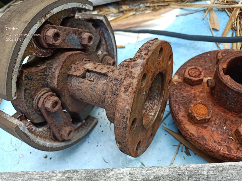 Cheers Aaron Off The Grid |
||||
| pd-- Senior Member Joined: 11/12/2020 Location: AustraliaPosts: 122 |
On the subject of keeping it quiet hear is what i built. The room housing the genset is an extension onto an existing mudbrick garage The engine bed was pored first with studs inbeded for the nisan patrol engine mounts that attach to the generators rigid frame. the concrete slab is isolated from the engine bed using expansion gap fome. The walls use steel studs packed with acoustic insulation " high density glass fiber " the surface of the studs have 2mm mastic tape attached then there is 12mm ply board then 6mm cement sheet on both sides inlet and exhaust cooling air passes through a long padded box with two right angels you can see the exhaust air from the radiator in the plywood enclosure The ceiling is just the plywood with acoustic fome on the inside then acoustic mats between the inside and outside tin roof any gaps are filled with expanding fome 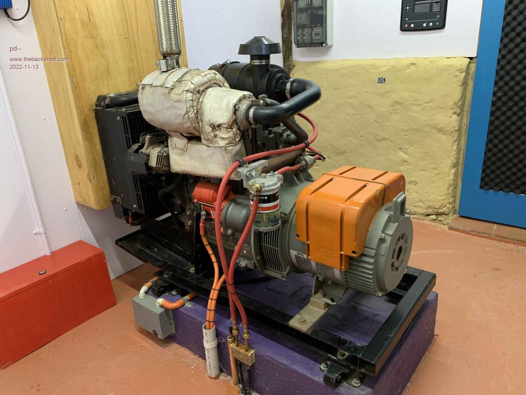 Edited 2022-11-13 20:36 by pd-- |
||||
| Davo99 Guru Joined: 03/06/2019 Location: AustraliaPosts: 1584 |
That is a very impressive and neat setup that's for sure! What engine and what size gen head? Looks substantial. How was the silencing in the end from outside the building? |
||||
| pd-- Senior Member Joined: 11/12/2020 Location: AustraliaPosts: 122 |
Its a Yanmar 3tnv84t 3 cylinder 1.5 L The alternator is a Leroy Somer 12KVA It is very quiet, you cannot hear it from the house. if you are out the front of the garage you can hear it but its about the same as my car idling. Before this i had a little Honda gx390 powers setup siting under a tin cover it would scare the chooks a kilometer away. Tips Plug every gap, i have on of thous fold down weather strips on the generator room door use lots of dense material plaster board , cement sheet The acoustic bats are a lot denser than standard insulation The denser they are the more expensive they get " no gaps" |
||||
| Revlac Guru Joined: 31/12/2016 Location: AustraliaPosts: 1151 |
Nicely done.  The slab and base frame is exactly the same as my father made, but we used DynaBolts on the mounts into the slab. Cheers Aaron Off The Grid |
||||
| The Back Shed's forum code is written, and hosted, in Australia. | © JAQ Software 2025 |
