Notice. New forum software under development. It's going to miss a few functions and look a bit ugly for a while, but I'm working on it full time now as the old forum was too unstable. Couple days, all good. If you notice any issues, please contact me.
MacGyver Guru Joined: 12/05/2009 Location: United StatesPosts: 1329
Posted: 04:27am 24 Aug 2009
Copy link to clipboard
Print this post
In a word, HELP!
Does anyone know the relationship between gauss, speed of permanent
magnets passing the coil and the number of turns of wire on the coil to
create 12-volts (actually around 13 to 15 volts for charging batteries)?
There has to be some formula that relates to a certain number of turns to
create a certain amount of volts, at least that's my hope.
I've done this before, but it's been like 40 years and I'd rather not
'reinvent the wheel' as it were. Unfortunately, I'm pretty good at that!
I'm spinning a plastic wheel imbedded with 1/4" neo magnets spaced 1/2
inch apart and each one is opposite the other, in other words one has it's
north face facing the pick-up and the next one is south all the way
around the wheel.
The magnets pass through a "C" coil of soft, flat-metal plates. The
clearance between the magnets and the coil on each face is a few
millimeters on each side. The field through the coil bounces back and
forth as each new magnet makes its way through the opening.
All I'm after is a small 12-volt charging mechanism. As you probably
already know, my windmills pump air and I use the compressed air to run
small air engines, which in turn spin generators. I realize this little
contraption produces AC; I'll rectify it if I ever get the voltage right.
I'm back to building my own generators again and that's where I am now;
like I said, HELP!Nothing difficult is ever easy!
Perhaps better stated in the words of Morgan Freeman,
"Where there is no struggle, there is no progress!"
Copeville, Texas
GWatPE Senior Member Joined: 01/09/2006 Location: AustraliaPosts: 2127
Posted: 05:39am 24 Aug 2009
Copy link to clipboard
Print this post
The coils in my AxFx mill are an example. On one phase with 12 magnet pairs, 50mmx12.5mm disks[N38], and 16mm between magnets, with the magnets centres at a 120mm radius, with 300 turns and spinning at 1Hz, gives approx 10VAC.
Physical layouts will play a significant part in your calcs.
Gordon.
become more energy aware
MacGyver Guru Joined: 12/05/2009 Location: United StatesPosts: 1329
Posted: 06:17am 25 Aug 2009
Copy link to clipboard
Print this post
Thanks GWatPE.
I'm looking for more of an a + b = c sort of thing.
Maybe I'm dry dreaming, but it seems to me there should be some fixed
relationship between a certain power of magnet (gauss) and the number
of coils it passes by to create a certain voltage.
I'm sure wire size determines amperage to a great part and in my way of
thinking, frequency is determined by speed.
I'm just looking for a 'nuts-n'-bolts' approach to this whole thing so as
not to create a giant birds next of enameled wire in my workshop trying
to get my generator to work!Nothing difficult is ever easy!
Perhaps better stated in the words of Morgan Freeman,
"Where there is no struggle, there is no progress!"
Copeville, Texas
MacGyver Guru Joined: 12/05/2009 Location: United StatesPosts: 1329
Posted: 06:20am 25 Aug 2009
Copy link to clipboard
Print this post
"giant birds next of enameled wire"
That should be birds nest. Funny how you can proof read a thing and not
see the obvious errors until just AFTER you've pushed the "Post Reply"
button, eh?Nothing difficult is ever easy!
Perhaps better stated in the words of Morgan Freeman,
"Where there is no struggle, there is no progress!"
Copeville, Texas
Greenbelt Guru Joined: 11/01/2009 Location: United StatesPosts: 566
Posted: 06:17am 26 Aug 2009
Copy link to clipboard
Print this post
MacGyver;
Electro magnetic induction;
The unit of electric pressure called the volt, is the electric pressure produced by cutting 100,000,000 lines
of magnetic field per second.
an example, A coil of 50 turns cuts 100,000 lines in 1/100
second will generate 5 volts. this info comes from a book
that was written in the 1930s ( AUDELS MATHEMATICS AND CALCULATIONS FOR MECHANICS. )Time has proven that I am blind to the Obvious, some of the above may be True?
MacGyver Guru Joined: 12/05/2009 Location: United StatesPosts: 1329
Posted: 05:04am 27 Aug 2009
Copy link to clipboard
Print this post
Thanks for the post. Does that mean that 10 turns produces 1 volt?
I guess I could just try it, eh?
Ultimately, that's probably how this thing will play out, but I just wanted to
go at it with a little more knowledge and not have my efforts turn into
Caveman 101!Nothing difficult is ever easy!
Perhaps better stated in the words of Morgan Freeman,
"Where there is no struggle, there is no progress!"
Copeville, Texas
GWatPE Senior Member Joined: 01/09/2006 Location: AustraliaPosts: 2127
Posted: 10:59pm 27 Aug 2009
Copy link to clipboard
Print this post
That would need to be one serious magnet, or spinning really fast past the coil.become more energy aware
Greenbelt Guru Joined: 11/01/2009 Location: United StatesPosts: 566
Posted: 12:23am 28 Aug 2009
Copy link to clipboard
Print this post
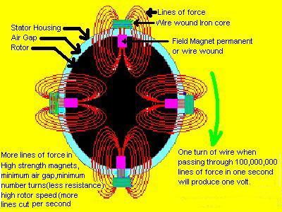
This graphic illustration of a 4 pole alternator (Maximum cogging) is to show the importance of having a good arrangement of hardware when building a generator. The best machine will be the one that captures the greatest percentage of the magnetic field (lines of force).
In the case of windmills there is a problem with having all the magnets aligned with the stator coils,The force required to pull loose of the magnetic attraction requires a fairly high wind but once it gets started the flywheel effect carries it through . In order to function in moderate and light wind the magnets are deliberately offset to cause half the magnets to pull in a forward direction while the others pull backward. this balance allows the turbine to start in very light wind.
Now an example ;
The 4 pole alt. has been wound with 36 turns #18 B&S enameled wire on each iron pole piece
To keep it simple, 4 Neo permanent magnets with a field of 70,000 lines each. can't cut all of em, but we'll fake it!
With all coils wired in series as if it were one big coil all turns wound in the same direction we now have 144 turns cutting 4 X 70,000 lines of force at 4 times each revolution. (144 X 70,000 = 10,080,000). (10,080,000 X 4 poles per rev.= 40320000).= 1-RPM . For voltage calculation the number of events in one revolution does not count,. The instantanous voltage of a single event is the system voltage However the number of events contributes to the total power of the system.(Ampere's). The wired coil magnetic flux occupies 90 degrees of stator circumference this means the neo mag will pass the coil in 1/4 the time of one revolution.
so every rev. counts as 4 times quicker cutting time. Note : it is the number of lines of force actually cut per second,. so it boils down to the number of turns in the coil and the speed of the rotor. To keep your generator within the speed of sound it should have a generous magnetic field.
So multiply the Number of turns that are cutting number of field lines in one second in one event. Then divide by 100,000,000.
The size of wire does not change this formula.
13.2 volts needs 100,000.000 X 13.2 in one second.= 1,320,000,000. At what speed will the alt. generate 13.2 volts.
I have posted this for the purpose of helping other people who are new at wiring coils.
There is much more to designing a good coil but a basic one can be made quite easily. Know the field strength of your magnet, convert specifications to field lines then know your speed of operation , from there, the voltage and number of coils can be worked out.
Impedance, reluctance, resistance. magnetic coupling, inductive reactance, hysteresis, Yea ! when you add all this
it probably will need twice as much-----Greenbelt
Time has proven that I am blind to the Obvious, some of the above may be True?
oztules Guru Joined: 26/07/2007 Location: AustraliaPosts: 1686
Posted: 10:27am 28 Aug 2009
Copy link to clipboard
Print this post
No amount of calculations will get you to where you want. To know all the variables would be very difficult.
The tried and true method is not to even try. Set up your magnetic paths however you want, and wind one test coil and place it where it has to go. find out how many turns per volt AC (not dc) and it is all simple from there.... ie let the natural laws of the universe work themselves out... and just use the results.
If you have ten coils in series then times 10, if it is 3... then x3.
For 3 ph phase then the no of coils in series gives you the phase volts at that rpm, and for star x 1.7 and to get the DC x1.4.... and you will be close.
Use any size wire you can lay your hands on for the test coil, and wind say 50 turns and work it from there.
You will need to know your intended cut in to be of any use though. Once you know the rpms for your best cut in (dictated by the blades length and it's TSR and how you wish to load the thing), you know how many turns it will take to achieve it. Fill the winding window with as much copper as you can reasonably get in there, and you will have the best coils setup for your design.
..........oztulesEdited by oztules 2009-08-29Village idiot...or... just another hack out of his depth
GWatPE Senior Member Joined: 01/09/2006 Location: AustraliaPosts: 2127
Posted: 12:45pm 28 Aug 2009
Copy link to clipboard
Print this post
I have to agree with you oztules. Do we really know how many flux lines the magnets we just bought on EBay have.
I just made a prototype, that allowed me to change the coil shape, the number of magnets, the magnet separation. I just used a vernier to measure spacers and coil sizes and a one and timing with a multimeter that could measure mVAC. Simple maths and some graphs gave a result that Phill tested with his mill which came out within a few % of what I had calculated. Good enough really.
For a windmill, I would not complicate matters by introducing iron to the alternating field path. Neo magnets are not really expensive now, so no need for the sub mm air gaps. I have made both extremes with AxFx windmills, and my latest alternator gets a gold star.
I have some complicated capacitor arrangements in order to use a stator that I would normally have remade, or scrapped. The use of caps is like an automatic transmission for the windmill, offering a loading reigime to the wind energy very close to optimum. Until you have first hand experience it does seem a bit complicated.
I have found that windmills are very forgiving between the two extremes of stall and runaway. The smoke and mirrors seem to be with the blades and furling. Too much of the time we are looking for the maximum power figures, rather than where the majority of the wind energy occurs at the site and design for that. My windmills have just produced a serious amount of power during the last storms, but it is more important for me to harness as much power during the low wind periods as well. The ability to maintain a battery relates to shedding peaks of power, yet capturing as much as possible of the low wind energy, to allow the absorbtion process to continue for as many hours as possible.
A 12V system is very difficult to manage without serious Ah batteries[probably 1-2000Ah]. You need shares in MIM holdings for the wiring. 24V, or 48V is the way to go. Battery cost usually determines system voltage unfortunately.
I suggest that you procure some magnets, and start experimenting. Go for a decent magnet size,[50mmDia], as it makes winding coils easier. If you can use a hacksaw, files, and other hand tools you could be well on the way to experimenting to get first hand data, without resorting to text books. Chances are you will use the magnets in the final design. Anyone can make these alternators with some laser cut parts, hand tools and some help from a fitter and turner for bearing assembly/shafts. I think the front wheel bearing assembly from a Ford Escort would do nicely, so there would be minimal machining.
Skimping on magnets and overpowering blades and mis-matched loading seems to be where most designs fail.
Gordon.
become more energy aware
MacGyver Guru Joined: 12/05/2009 Location: United StatesPosts: 1329
Posted: 05:26pm 28 Aug 2009
Copy link to clipboard
Print this post
I should clarify this a little. I'm attempting to build a "stationary" electric
generator. It sits on a bench in my little shop and I turn it with an air
motor that runs off compressed air. My "windmill" compresses air.
That being said, there are no worries about cut-in and cut-out speeds or
anything that has to do with a traditional wind turbine. My air flow is
governed and is constant.
Oztules:
It looks like you're right and I'm just going to have to do this from scratch.
I was hoping to avoid having to "reinvent the wheel" but it looks like there
are so many variables, it'll just have to go down that path.
My goal in all this is to create a very simple, easy-to-build, cheap
generator that folks can use to recharge 12-volt car-type batteries.
When I come up with the final product, I'll post the critter here and on my
up-coming Web page (it's on my to-do list!).Nothing difficult is ever easy!
Perhaps better stated in the words of Morgan Freeman,
"Where there is no struggle, there is no progress!"
Copeville, Texas
oztules Guru Joined: 26/07/2007 Location: AustraliaPosts: 1686
Posted: 11:22pm 28 Aug 2009
Copy link to clipboard
Print this post
In that case, I assume there is a reciprocating part of it that will have a sweet spot (ie happy rpm area). That will be the spot to aim for I figure for the RPM's for your 14v.
ie We need to develop 14v at the lower end of the sweet spot... gives you your "cut-in", economic run speed, and room for "boost" and still be in / near the economic power zone.... so to speak.
However your motor works to drive it, a test coil will reveal all about your alternator magnet geometry.... without having to wind the whole thing and end up with
your rats nest.... just a rat coil.
.........oztulesVillage idiot...or... just another hack out of his depth
GWatPE Senior Member Joined: 01/09/2006 Location: AustraliaPosts: 2127
Posted: 12:17am 29 Aug 2009
Copy link to clipboard
Print this post
I probably should have gone back and read the original question again.
The grade of the iron in the C-section is presumably unknown.
Just spin the rotor with the air motor, with a few test turns around the C-section. measure the output AC emf. Simple calcs will give the electrical relationship of the coils.
I suspect that what you are doing will benefit your personal setup. I have not seen or heard of anyone else storing compressed air this way. Prior to battery hand tools, I used air tools in a workshop environment. This was a safety aspect, not because compressed air was better at providing the power compared to electricity. Unless you have huge volumetric storage, either in capacity, or pressure, the energy density of a battery will be superior.
I feel that most punters would not benefit much from an extra conversion step of an air intermediate.
I do like the way an air windmill behaves to loading. This is similar to comparing solar panels and windmills with the manner in which battery regulation is achieved for the electrical equivalent.
I see the compressed air concept simplifying the loading/regulation of windmills to a battery load, but I have found that rotor furling and windmill electrical shutdown achieve similar results without an intermediate storage system.
Good luck with your prototyping.
Gordon.
become more energy aware
MacGyver Guru Joined: 12/05/2009 Location: United StatesPosts: 1329
Posted: 03:51am 30 Aug 2009
Copy link to clipboard
Print this post
The way this started is I build small steam and air engines for my hobby
and built the compressor windmills as a way to have a constant supply of
low-pressure air without my compressor going thunkity-thunk in my
garage for hours.
It turns out that using compressed air makes controlling a generator with
a changing load situation easyly facilitated by using a standard governor.
When the load increases, the valve lets more air through the air motor
and so on.
As far as air storage capacity, you're right; I'm a plumbing contractor and
have access to lots of water heater tanks that are replaced "just because"
that don't actually leak. I link these in parallel and use check valves to
isolate them from "accidents" (leaks). My side yard has a lot in common
with the set from Sanford & Son, the TV show about a junk yard guy.
At this stage of the game, I'm attempting to build my own generator from
scratch. Up to now, I've used off-the-shelf car generators and
alternators. I just want to build my own, that's all.Nothing difficult is ever easy!
Perhaps better stated in the words of Morgan Freeman,
"Where there is no struggle, there is no progress!"
Copeville, Texas
MacGyver Guru Joined: 12/05/2009 Location: United StatesPosts: 1329
Posted: 04:01am 30 Aug 2009
Copy link to clipboard
Print this post
Ooooooh! Is it me or did everyone else just experience a ripple in the
Force? (Senior status appeared as if by magic!)
GWatPE:
The "C" coil is a snap to build. I merely take apart a little 110 vac fart fan
(that's what they call them) and cut out the portion that holds the stator.
It's what is called a 'shaded-pole' motor and I use the flat soft plates
because they conduct magnetic flux lines really well. I pull the windings
off the exiting coil and re-wrap it with larger wire. I grind a slot where
the stator was to accomodate the little 1/4" new magnets, which are
press-fit into a wheel that I spin with an air motor.
That's it.Nothing difficult is ever easy!
Perhaps better stated in the words of Morgan Freeman,
"Where there is no struggle, there is no progress!"
Copeville, Texas
GWatPE Senior Member Joined: 01/09/2006 Location: AustraliaPosts: 2127
Posted: 05:41am 30 Aug 2009
Copy link to clipboard
Print this post
You have reached the pinacle now. No more goals past Senior.
Back to the C. I gather the air motor/magnet rotor is made? Just place a single coil on the C and turn ON the air. At the expected system pressure, what is the output ACV from the single coil?
BTW, how do air motors last in continuous operation. I remember difficulties with oiling on high speed units. Rattle guns, and air drills are low duty cycle items. How do these air units you make go 100% duty cycle for months at a time? Yearly service would be acceptable.
It will be a simple task to calc turns for 12V system, unless there is more than 12VAC for the one turn.
Gordon.
become more energy aware
oztules Guru Joined: 26/07/2007 Location: AustraliaPosts: 1686
Posted: 09:00am 30 Aug 2009
Copy link to clipboard
Print this post
Hmmm.
The steel laminates are good candidates for this type of thing, but the problem I see for you will be the magnetic path efficiency. If yours are like the one I rewound the other day for a fan heater (3 speed... nearly 1800 turns including the tapped windings)... then I see you dumping a fair bit of your flux through the short circuit that holds the thing together.
The circular hole that the rotor goes through, is where you are going to cut the magnet slot.... but that leaves the part of the circle that is in parallel with the bit you press out .... (otherwise it wont hold together).
This magnetic "shunt" will cost you a good deal of Flux leakage... meaning bigger magnets again, or reasonably inefficient generator, with higher resistance than otherwise without that shunt effect. For good 12v operation, low resistance is a must I should think. If the energy is free (wind directly), you can live with this, but having to catch, store and then waste it is something else.
The other thing that may be a bother to you is the vibration from the magnets passing the steel stator. If you use 14 magnets and 11 "C's", this may mitigate the vibration and effective cogging effects... rectify each coil separately.
Things to ponder
.........oztules
Edited by oztules 2009-08-31Village idiot...or... just another hack out of his depth
MacGyver Guru Joined: 12/05/2009 Location: United StatesPosts: 1329
Posted: 05:33pm 30 Aug 2009
Copy link to clipboard
Print this post
Grandkids are over for the weekend, so I can't experiment much until
next week/weekend.
That being said, I'll try these several suggestions and get back to yall. For
now, I'll address several concerns from the above replies:
As far as vibration from magnetic cogging, no worries: Only one C-coil
thing! I told you I liked keeping things "simple"!
On longevity: The "motor" is made of latex rubber tubing (usually) and it
for sure won't last years and years. After a while the inside somehow gets
"sticky" and messes up. No worries, I just slide in another chunk of
tubing. I gotta figure out how to post pictures on this 4m; that would
solve a myriad of problems.
I also have a motor that uses flat latex sheet, but it has lots of interesting
habits, so I only use it for "demonstration" purposes. I've toyed with the
idea of using a different material than latex sheet, but like about a zillion
other things, it's on my "to-do" list.
As far as the big hole where the stator is missing, you're absolutely right,
it's not the 'best' but it's what I use and it's easy. I'm all about easy and
simple. The only thing approaching that kind of simplicity is a bicycle
generator (alternator). I've made some, but they too are kinda tricky.
Glen:
I'm toying with building a Web site with all my crap on it, but it is not my
desire to draw folks away from the 4m, so maybe instead I'll just post all
the stuff here.
Fortunately or unfortunately, it'd take up oodles of space and I don't want
to monopolize your territory, so I guess that creates somewhat of a
dilemma, eh?
If I do my own Web site, it won't be for profit; that's not my motive, but
there will be several "parts" that will require the builder to own a lathe or
mill or both and I was going to offer "care packages" online for those, so
I'd have to charge something just to make it work, I guess.
What say you?
GWatPE:
How do you make that little box thing for quotes?Nothing difficult is ever easy!
Perhaps better stated in the words of Morgan Freeman,
"Where there is no struggle, there is no progress!"
Copeville, Texas
I have done a lot of testing on a number of areas for generating power. I have found a lot of flawed info, many seem to follow what every does.
I am a retired tech, I will try to post a pic not sure how it will work on this forum.
The so called flux lines that every one seem to go with is the formation of iron filings on a piece of paper, this has now been proven to be incorrect.
The main lines that produce a ‘force’ as in grams or kg is not the same.
If you can get a gauss meter you could prove it your self if you know how to work them correctly.
The gauss reading is the ‘field strength’ of the magnet , ‘grenbelt posted a pic and some information on calculating the voltage, I have no idea where he got this stuff from, I would be interested to know.
The pic that I will try to post four of them show you the field strength of a circular rod mag. I have found out a lot of stuff to do with wind turbines and the way that most of you are connecting them and a whole lot more, it shows that most of what is being ‘followed’ is wrong, even Hugh P’s wind turbine.
aussepom
it seem that I can not see how to post a pic let me know how and I will post them
Downwind Guru Joined: 09/09/2009 Location: AustraliaPosts: 2333
Posted: 03:33pm 10 Jun 2010
Copy link to clipboard
Print this post
Ausseporn,
I posted a how to post photos in windmills for you in the last thread you commented on.
Pete.Sometimes it just works
Page 1 of 2
Print this page
The Back Shed's forum code is written, and hosted, in Australia.