
|
|
Forum Index : Other Stuff : recharging cellphone by dynamo
| Page 1 of 2 |
|||||
| Author | Message | ||||
prez123 Newbie Joined: 07/02/2010 Location: IndiaPosts: 1 |
i want to recharge my cellphone through a dynamo to which windmill type blades will be attached.my cell needs 5V , 890 mA for its charging. so i wanted to know how much ll b the dynamo output if wind speed is 60mph?? im gonna clamp the dynamo on the window(here im talking about the trains in my country i.e INDIA).. how to limit the dynamo output such that my cell is not damaged?? plz help ppl.. :) prez |
||||
Downwind Guru Joined: 09/09/2009 Location: AustraliaPosts: 2333 |
You Indians do some wierd sh*t! A lot of the things we do with wind is trial and error testing to get things right. I doubt anyone can give you a blue print of a wind phone charger out of thin air. What is the dynamo output you are using and what rpm is that output tested at. How many amps do you get at the test rpm. What sort of blades are you using. Best you do some field research and testing then we might be able to help you with the finer points. Pete. Sometimes it just works |
||||
KarlJ Guru Joined: 19/05/2008 Location: AustraliaPosts: 1178 |
must take about 10mins to charge at that current! try for something like 5V and 100mA http://www.thebackshed.com/windmill/assemblyMini1.asp this is easy, almost free and will do the job as long as it makes better than 5V. Luck favours the well prepared |
||||
| Downwind Guru Joined: 09/09/2009 Location: AustraliaPosts: 2333 |
Prez, Firstly to bring others up to speed here. In a PM you say you are looking at using a stepper motor, a bridge rectifier and 120mm dia blades. There is still a lot of guess work involved here. For one i dont know how a stepper will preform in 60 mph wind speed with 120mm blades. I am thinking this might be too fast for a stepper. When i played with a stepper some years back i needed about 400-600mm dia blades to overcome the cogging effect but i also didnt have 100kph wind speed. 2) Depending on the type of stepper (bipolor or unipolar) will depend on how many wires it has. This will change how many bridges you need. For interest if it is a basic 4 wire bipolar than you will need 2 bridges, one for each set of coils. The dc outputs would be paralleled together. The other thing to consider is what sort of battery you are charging and what charging controls is needed to do this. If your phone has a lithum iron battery i would not even attempt this without knowing a lot more, or you might blow it up.....BANG.........Smoke...... 
What tools do you have, a multimeter, soldering iron, electric drill,etc, do you have access to a car that you can do some speed testing with? What electronic knowledge do you have? There is a lot to consider for a simple project. Atleast so it will work without damaging something or someone. For interest i got a smallish bipolar stepper from an old laser printer and spun it in the cordless drill at around 1500rpm and got 5.5volt dc at 0.5 amp. but without a 0.5 amp load the voltage went up 22 volts so some form of regulation will be required or as the battery gets near full charge it will be overcharged at a higher voltage. Pete. Sometimes it just works |
||||
| Gizmo Admin Group Joined: 05/06/2004 Location: AustraliaPosts: 5186 |
What about using a simple shunt regulator made from 8 diodes in series. Each diode drops 0,6 volts, so 8 in series would regulate the wind turbines output to 4.8 - 5 volts. The diodes would get warm, but in a 100kmh air stream they should stay cool enough. Could a DC motor from a toy or battery drill be used, with a fan from a PC power supply? I once held a PC fan out the window of my car an 100kmh and it was blistering fast. Glenn The best time to plant a tree was twenty years ago, the second best time is right now. JAQ |
||||
| Downwind Guru Joined: 09/09/2009 Location: AustraliaPosts: 2333 |
I must admit i to considered surgesting using one of those dc fans that the taxis over there, use to have stuck to the dash, that bathed you in hot air. I dont know if they still have them or if one would work well enough. Also considered gutting a pc fan to use as a generator as they are basically a 3 phase motor but doubted if you would get enough current out of one. You could try the fan/motor out of a old hair dryier if you can find one. How long is your train ride? Pete. Sometimes it just works |
||||
| Downwind Guru Joined: 09/09/2009 Location: AustraliaPosts: 2333 |
Prez, Please keep this on the forum and not through PM's. [quote]the train ride ranges frm 15 to 20 hrs. the top speed will be 110 kph, average will range frm 90-100 kph. click below to see how our indian train window look like. http://i.telegraph.co.uk/telegraph/multimedia/archive/01240/ india-train_1240384c.jpg so u can understand size matters here. the size sud be such that u can stick the device out and clamp on the window rod. (1)Sud i use a DC motor rather than a stepper motor? which one could bear HGH RPM without being getting damaged? (2)Can i use a damper to reduce speed in case of stepper motor without compromising the overall size? listen, pete i said fan dia sud be 60 mm, not 120mm as you are saying. [/quote] The link for the train window did not work...not found. Ok 60mm dia fan i dont think has a hope in hell of driving a stepper motor. It might drive a toy dc motor but at a much reduced current output...maybe 100mA if you are lucky. Best rethink the project and not rush into it, as i cannot see it working as you would like. Pete. Sometimes it just works |
||||
MacGyver Guru Joined: 12/05/2009 Location: United StatesPosts: 1329 |
prez123 The trains in my country (USA) have onboard plug-in 110 vac for folks to plug in computers and such. You might want to see if your train system offers something similar and just take your home charger with you on the train. Okay, that's maybe a stupid suggestion, so if it were me about to hang a wind charger out the window (gotta be some rules on that sort of thing, ya think?) I'd make a system that could charge a battery large enough to use as a buffer between the gale-force wind just out the window and the battery in the cell phone. That way, if the train were to say, head upwind and the outside wind speed doubled for a mile or two, you would run less risk of frying your cell phone's electronics, eh? Just a thought, but if you were to use an intermediate battery, you would likely be able to look up some known values for voltage & amperage input and so on as there has been lots of research on that sort of thing already. Might be good to cary two phones just in case you bar-b-q one of them!  Nothing difficult is ever easy! Perhaps better stated in the words of Morgan Freeman, "Where there is no struggle, there is no progress!" Copeville, Texas |
||||
oztules Guru Joined: 26/07/2007 Location: AustraliaPosts: 1686 |
I vote for Gizmo's solution. A 3" diam computer fan would run at about 6600 rpm (tsr 1?? maybe) loaded at 60 mph. Prop power should return about 16w max. Being an iron cored machine, you could hope that armature reactance will current limit the fan output current and prevent burnout????... rpm may rise to perhaps 10000 rpm. Then the shunt diodes of about 1-2 A should hold it down without difficulty. It will depend in the wire thickness, but I suspect 100ma would be within reach. I would try this into 3 AA cells first to test the current and the heating of the motor and bearings. A 2" one would run 10,000 loaded and develop 7-8w at the shaft. At least this is compact and relatively safe to fiddle with. A car test would ascertain if it will handle the forces and current involved. Iron core may save the situation fairly well..... but I would keep the fingers away from the tiny rotors just the same. There is a remote chance that unloaded at these rpm, it could make 80-90v, and run the AC charger too. That would be the best outcome. ..........oztules Village idiot...or... just another hack out of his depth |
||||
| Downwind Guru Joined: 09/09/2009 Location: AustraliaPosts: 2333 |
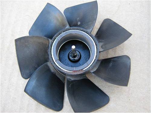
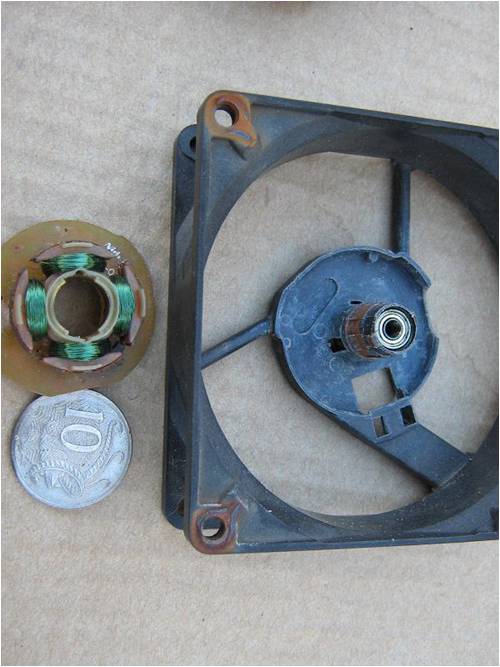
Over the last few days when i had a spare hour or so i had a play with a fan from a computer power supply, 75 mm dia. fan. 80mm overall case size. They are a difficult little thing to get apart without destroying them. The first 2 i tried, i wrecked them getting them apart, by the 3rd one i had worked out how to disassemble them, but still not an easy task. Once all disassembled the circuit board was removed leaving the 3 pins that the phase windings are attached to. 3 wires was soldered to the pins and the fan reassembled. 2 diodes were attached to each phase wire to form a 3 phase rectifier. Holding the fan out the window and driving at 100 kph the fan produced around 20 volts unloaded. With the dc leads shorted it produced around 220 mA and 0 volts. With a 27 ohm resistor as load it produced about 180 mA at 5.5 volts At 80 kph it produced about 150 mA at 4.5 volts (27 ohm load) With a 4 diode shunt i got about 3.2 volt output. (5-6 diodes would be better) The fan ran better when held backwards to the wind but would not recommend running it this way as all the thrust is on a tiny cir-clip and not the wear plate on the shaft. In first tests i had the wire mesh grill on the front of the fan but removed this thinking it might have been interfering with the air flow. It made little difference and was a mistake to remove it as the fan then bit a chunk out of my finger. All figures are approximate as it is hard to drive, hold a fan and read 2 meters on your lap, hence finger damage. The fan produces a Vrrool whirling noise at high speed that would drive me mad with a open window over a period of time. Pete. Sometimes it just works |
||||
| oztules Guru Joined: 26/07/2007 Location: AustraliaPosts: 1686 |
Well tested. It looks like a simple and safe way to run the thing (with the grill on) The fact that the grill made little difference makes me think that the iron core and fan solidity will protect from overload. Looks like the power figures were in the ball park, and with only 1 watt or so from a possible 16W @ 60 mph our CP will be less than .1 fan solidity and grill and reactance and resistance.... take your pick. It was a good test, do you recall how things were at 30 mph? ..........oztules Village idiot...or... just another hack out of his depth |
||||
| Downwind Guru Joined: 09/09/2009 Location: AustraliaPosts: 2333 |
Hi Oz, No i dont recall 30mph but will do a retest to find out. Is there any thing else you would like a test done on for more information while i am at it. Might bolt the sucker to the roof racks this time, as holding it, was not the best way for testing. (not to mention the strange looks i got from other motorists) I had considered how 2 fans would preform screwed back to back, but thought the turblent air off the first fan would not work well with the second fan....any thoughts. This is something i dont intend to spend a lot more time on, as of little use to me, but thought i would test the theory seen i had the junk lying around to do it with. Pete. Sometimes it just works |
||||
| KarlJ Guru Joined: 19/05/2008 Location: AustraliaPosts: 1178 |
Nice one Pete 
5V and 180mA is something decent enough to work with for this purpose. As they are almost free (junk) the bearings probably wouldnt matter that much as you would throw it away every week! Luck favours the well prepared |
||||
| Downwind Guru Joined: 09/09/2009 Location: AustraliaPosts: 2333 |
I dont think the bearings would give too much trouble as they have 2 good sets of roller bearings on the shaft. But then again travelling at warp speed anything could happen. Over all quite well made little units for what they are. pete. Sometimes it just works |
||||
Sonny Regular Member Joined: 17/01/2010 Location: United StatesPosts: 66 |
I know this may sound stupid but I was thinking, how about one of the little generators made for bicycles. It wouldn't take much to make up a set of blades for it or maybe get a model airplane prop and modify it to work. It might generate more current then you need but that should be an easy fix. After all bicycles are big in India aren't they? a complete novice |
||||
| Downwind Guru Joined: 09/09/2009 Location: AustraliaPosts: 2333 |
I remember back in school days i had a mini bike that i put a bike dyno on the front wheel for a night ride. I think it lasted about 10 minutes at 60 kph before it glowed red in the dark. Then i was in the dark...no more light...........(used a dolphin torch then.. more reliable) Also the brief was for a 60mm fan/blade size and there is no way that dia. blade would drive a dyno. It would have been a easy solution other wise. I do have one some where so will stick a pc fan blade on the end and try it, just for the hell of knowing if a 75mm fan will run it or not. ...dont like the chances. Pete. Sometimes it just works |
||||
| oztules Guru Joined: 26/07/2007 Location: AustraliaPosts: 1686 |
Thanks for that Pete. It was just curiosity. For 3" fans, there should still be a few watts @ 30 mph in the wind. (probably close to 6w @ CP=1) Just wondering how the CP held up as the rpm dropped off. If CP rose(from woeful to not so woeful), and power didn't drop off dramatically, we may have been in solidity and or reactance from 30 odd mph onwards. This would give us a chance to see self regulated alternator/blade combo's in action.... albeit in small scale. Just curious. Karl, some of the earlier ones used ball bearings.... I have never seen such little ball races. ........oztules Village idiot...or... just another hack out of his depth |
||||
| Downwind Guru Joined: 09/09/2009 Location: AustraliaPosts: 2333 |
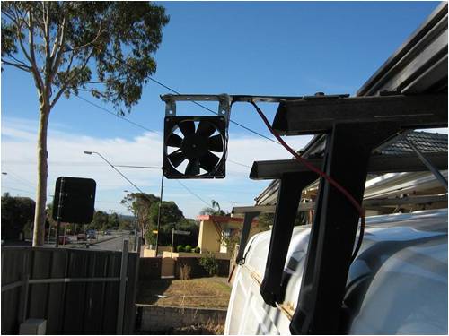
You know what curiosity done to the cat?? I done some more testing with the pc fan set up as a generator This time mounted to the roof rack on a van. This more than likely caused some error in the results as it is like a brick travelling through the air to start with. Also noticed the turbulent air from any vehicle travelling in front also effected the readings. The speed was taken from a GPS within +/- 1 kph. It would have been better to conduct the tests on an open road in a vehicle that had cruise control. Then repeat the test travelling in the opposite direction to eliminate any wind speed differences. But it wasn�t done this way!! Rather a brick belting around suburban roads, while trying to read 2 meters and record results switching between open and closed circuits. (room for error) The wind speed at time of testing was about 10 kph, and I changed direction of travel so many times I can not say how the wind played into results. The load used was a 27 ohm 5 watt resistor. The fan was facing forward. 2 sets of test were done one without the wire guard fitted and one with the guard fitted. It took around 20 kph to get the fan to start. (over come cogging) The mA reading is only when load was connected (closed circuit) otherwise it was a zero mA reading (open circuit) [code] Without the wire guard attached Speed kph mA open volts 27 ohm load volts 20 40 2.2 1.2 30 60 7.8 1.5 40 70 11.7 1.8 50 100 12.2 2.6 60 140 15.1 3.2 70 160 20.2 4.2 80 180 21.0 4.6 90 190 22.5 5.1 100 220 26.2 5.9 110 230 --- 6.1 ------------------------------------------------------------ ------------- With the wire guard attached 20 --- --- --- 30 --- --- --- 40 60 10.0 1.6 50 100 8.2 2.5 60 140 9.7 3.2 70 150 11.2 3.6 80 160 20.1 4.3 90 180 --- 4.8 100 190 --- 5.2 [/code] A few photos of this monster we are dealing with here. 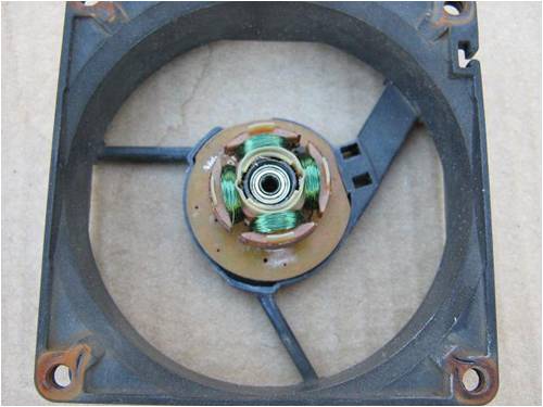
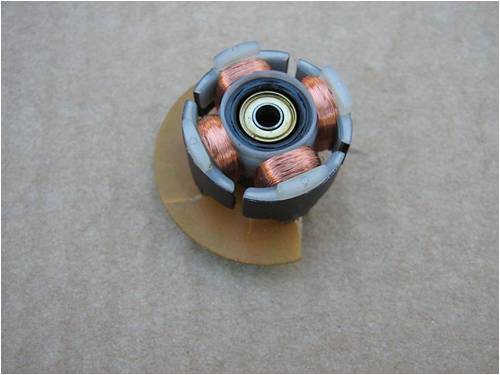
Great little roller bearings 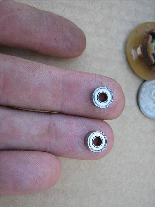
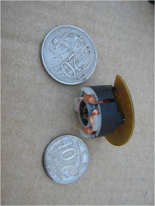
The retaining circlip to show why i say not to run the fan backwards 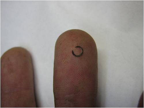
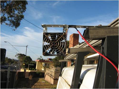
As prez123 has not par-taken in this discussion and i feel i have done more than required to test this theory and am about done with this. Its been a fun project but of little use to me. I am curious of what Oz makes of the data. Maybe with a 1000 or two of these i could pump some power back into the grid 
Happy to answer any questions but .....end of project!!! Pete. Sometimes it just works |
||||
| KarlJ Guru Joined: 19/05/2008 Location: AustraliaPosts: 1178 |
Pete, I think you have too much time on your hands. Time to set your mind around the AXFX thing with Phill and Gordon so you can feed the grid with some REAL power. Oh and where's the post for the killer bridge recs? I'm sure everyone else wants to see them too
Luck favours the well prepared |
||||
| Downwind Guru Joined: 09/09/2009 Location: AustraliaPosts: 2333 |
Gee.... Karl you nag worst than a wife. (besides you only put in, and not put out) 
The rect's are coming, just need the time to get the bits tgether. Should have some time over the weekend now the fairy fan generator project is over. Also need to build a 4000 watt resistor to test the rect's hard, even though in most operations they will only see 1/10 of that. Still hard to compete with the Chinese ones you have posted links for. The fan thing was about an hour a day for the week....what else do we do when not at work....watch tv???? Would luv to build a AXFX but still cant fly it here
Pete. Sometimes it just works |
||||
| Page 1 of 2 |
|||||
| The Back Shed's forum code is written, and hosted, in Australia. | © JAQ Software 2026 |
