
|
|
Forum Index : Other Stuff : alternator generator
| Author | Message | ||||
rouge Newbie Joined: 19/05/2010 Location: Posts: 11 |
Hi, I decided just for kicks to see how much power I could get out of an alternator using a bike to power it. I know the alternator is horribly inefficient and this is not the best way to try and produce power. But i still thought I'd try it out and see what I could get. attached is my wiring diagram, could anyone please comment on if it is correct or not? I understand that the sense wire runs to the b+ output on the alternator, and that the green wire that comes out of the alternator clip needs to go to ignition in a car or some way to excite it so i put that on a switch with a battery at the other end. and then for ground i am using the alternator frame.When I am pedaling at about 2000 rpm i only get out about 80 mA and about .4 V out of the alternator. I thought 2000 rpm would be enough to get some current out of this thing because when your car is on it is not always above 2000 rpm and at that rpm the alternator is running just fine in a car. i don't expect to get nearly the same amount of current out of it. And i assume the alternator is turning at about 2000 rpm because for each turn of the crank shaft the alternator turns about 22 times. so when i am pedaling at 100 rpm that should mean the alternator is turning at about 2000 rpm. Anyone have any possible suggestions of what I am doing wrong? Thank you 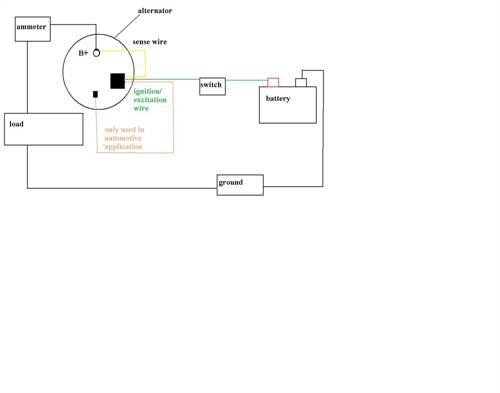
|
||||
| Robb Senior Member Joined: 01/08/2007 Location: AustraliaPosts: 221 |
Well this is the circuit Glen uses: 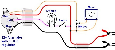 
Click here for context. |
||||
Downwind Guru Joined: 09/09/2009 Location: AustraliaPosts: 2333 |
Is your alternator with a built in regulator or without? If its external reg than you are best to use it with the external reg added to the circuit. It will work without the external reg but you need to add resistance to the wire going to the field windings to control the output. Also in your schematic you have no wire to the + side of the battery or no earth from alternator frame to battery. If you have wired it as drawn it is almost open circuit.(it wont work) A earth wire between battery (-) and alternator frame might make a big difference to operation. Pete. Sometimes it just works |
||||
| rouge Newbie Joined: 19/05/2010 Location: Posts: 11 |
sorry the alternator is out of a 1992 ford ranger, it is made by duralast. it has an internal voltage regulator and is considered a "1 wire" alternator i believe, and i'm sorry i thought i had mentioned that the ground i am using is the bolts that attach the alternator to its bracket and i am sorry i didn't mention before i am not trying to charge the battery in this situation, i am only using the battery to excite the field in the alternator so that it will produce power. and i am sorry do you mean i need to run an additional ground wire from the negative battery terminal? thanks for your help. and i initially checked my diagram against the one that is posted on the site earlier today in his gasoline motor powered generator(battery charger/0 |
||||
| Downwind Guru Joined: 09/09/2009 Location: AustraliaPosts: 2333 |
Hi Rouge, No need to be sorry, we are all here to help each other. YES...you do need a negative wire between frame and battery negative or you will not excite the windings. In the car it is a one wire connection as negative is a common earth to all but in your setup it is presently open circuit. Add the negative connection and give it a whirl i think it should work then. Let us know how you get on. Pete. Sometimes it just works |
||||
oztules Guru Joined: 26/07/2007 Location: AustraliaPosts: 1686 |
I urge you to use a globe in series with the switch going from the B+ to the ind terminal. This terminal expects some 12 bias from the globes resistance, but only to get the +brush with some initial external +. Once it gets going, there are three small diodes that connect to this point from the main windings, providing positive for the rotor field. If this gets directly connected to the battery through your switch, and you put in your ground return, you run the risk of these little diodes trying to recharge the battery, instead of the big diodes designed to do it.... this usually means smoke in a few seconds. With the globe in series, it gives the rotor field enough magnetic effect to get the main fields working, and then it easily provides for all + voltage to the positive slip ring. With the globe installed, it does not try to backfeed the battery. The regulator then pulses the negative slip ring to ground. So the positive slip ring is basically tied to a positive source, and the negative one is the one that controls the output. ............oztules Village idiot...or... just another hack out of his depth |
||||
| rouge Newbie Joined: 19/05/2010 Location: Posts: 11 |
downwind: thanks, i have a wire running from the negative terminal on the battery directly to the alternator frame, but still no luck with producing anything at all. unless i am mistakenly understanding as what you are trying to communicate. oztules: i'm sorry i do not understand what a globe in series is? i tried googling it and i didn't get anything that would relate to wiring. would you please explain what globes are? |
||||
Greenbelt Guru Joined: 11/01/2009 Location: United StatesPosts: 566 |
rouge wrote; i do not understand what a globe in series is? A globe is Old English for what we know as a light Bulb, In series means, Cut the wire and Join it back together using the Light bulb as a link. It can be done as illustrated but a bulb socket is desirable, an instrument panel bulb will give a start up field current. Do not use a large bulb 
Edit Robb Has Drawn a very good circuit diagram for your project. Just connect the little alligator's to a battery, A 12 volt Lamp battery taped to the bike frame with a switch to break the circuit after pedaling begins. BTW, You have not specified the load you will place on your alternator, if not to charge a battery then what? A Light a Motor?? There is no output from a generator when it is not loaded. Also Check the Diodes in the alternator, if it is a used one you may have to Buy a diode -regulator package for it. They blow out when a battery is connected with reverse polarity.( Jump starting) most common. good Luck. Time has proven that I am blind to the Obvious, some of the above may be True? |
||||
| Gizmo Admin Group Joined: 05/06/2004 Location: AustraliaPosts: 5022 |
Hi Rouge. You need to rewire the alternator to its simplest possible circuit. Take out anything that might be causing a problem. The light buld ( globe ) can be the indicator bulb from your car, any 12v light under 30 watts will work ok. 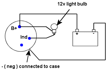
If you connect it up like this, the light bulb should be lit up. Hop on and start pedpedling. When you start to pedal fast enough, the light bulb will go out and the pedling will suddenly get very hard. That means its working. Let us know how you go. Glenn The best time to plant a tree was twenty years ago, the second best time is right now. JAQ |
||||
| rouge Newbie Joined: 19/05/2010 Location: Posts: 11 |
terrific thanks for the help guys, so following everyone's instructions and thanks for the diagram gizmo, so I got the alternator underload and yes it did become much more difficult to pedal. In fact the pulley and belt start to slip a little now, but thats not a big problem to fix, So i guess i have some general theory questions left if the board doesn't mind answering, 1. so all the voltage that the alternator generates won't that be just stacked on top of the battery voltage? and the voltage generated by the alternator is limited by the internal regulator which is why the sense wire is needed right? 2. then what is the best way to measure output power of this alternator? I was trying to measure it by having it hooked up just a bunch of light bulbs and measuring current and voltage that way with the battery out of the loop. I didn't want the battery to interfere with my readings. But now it looks i have to have this battery directly hooked up to the alternator in order to get it working. So if this question makes sense, what is the best way to measure power output since the battery is putting out current to the alternator to get it started? eventually i am going to use this device to power a battery hopefully, we will see how well it does, but just at first i wanted to get a sense of what the alternator could put out. thanks once again |
||||
wind-pirate Senior Member Joined: 01/02/2007 Location: CanadaPosts: 101 |
Hi Rouge Google alternator secrets "author unknown" You will need pdf to read it. It has Some excellent info about auto alternators. And how to better them for wind and personal use. Ron THE Pirate. stealing wind & solar energy is fun |
||||
GreenD88 Senior Member Joined: 19/05/2009 Location: United StatesPosts: 104 |
Alternator Rewinding (Instructables) Here's someone rewinding an alternator to try and get lower RPM voltage. Looks like he messed up his windings the first go around but got 12v at 550rpm. I'm gonna keep my eye on it and see after he fixes the windings what what rpm gives him 12volts. Licensed Master Plumber / EPA 608 Universal License / 410a Safety Certified / Medical Gas Brazer/Installer |
||||
| Downwind Guru Joined: 09/09/2009 Location: AustraliaPosts: 2333 |
Good to hear you got it to work. All i can say now is .....On Ya Bike..... Pete. Sometimes it just works |
||||
| Robb Senior Member Joined: 01/08/2007 Location: AustraliaPosts: 221 |
Insert ammeter here: 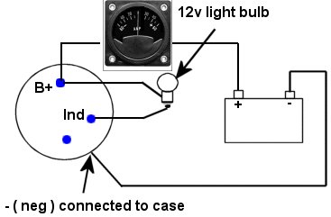
The meter should start out just in the negative side when the lamp is glowing and swing posative when you start making power. Alternativly use the battery lead for a as a shunt as Glen did here: |
||||
| rouge Newbie Joined: 19/05/2010 Location: Posts: 11 |
terrific, thanks Robb for your help, this gives me a bit to work out, I appreciate all this help. |
||||
| Greenbelt Guru Joined: 11/01/2009 Location: United StatesPosts: 566 |
rouge One little Bit to add... The + terminal on the Ammeter connects to the B+ on the alternator and the (- Terminal connects to the + Battery terminal.) Time has proven that I am blind to the Obvious, some of the above may be True? |
||||
