
|
|
Forum Index : Other Stuff : Kaplan Turbine
| Page 1 of 2 |
|||||
| Author | Message | ||||
Woodsworks Newbie Joined: 16/08/2010 Location: New ZealandPosts: 9 |
Hi, just joined up, and this is my first 'new topic' post. I have a decent sized stream running through my property, not much fall to speak of but respectable flow, in the order of 50L/sec (that's about 11 gallons). It is fed by a spring and hardly varies summer or winter. A kaplan turbine seems like a good choice to extract some power. I thought about an undershot wheel, but damming the stream presents some issues with saturating the very porous soil higher up the banks. What I can do is build a small weir further upstream and carry the water in a 200mm drain pipe or suchlike along to where the bank of the creek has subsided to leave a big depression where I can park the turbine - happily this is also in line with my house so power cables are as short as possible. Question is; Does anyone out there have any experience with small kaplan turbines? I'm looking for some idea of what diameter runner I should look for. I have a six-bladed fan made from stainless steel and aluminium that could work, but at 280mm diameter, is it too big for the amount of flow available? I have made the acquaintance of another local RE aficionado who knows a bit about F&P drives and has one I can steal, so that is most likely what I will be attempting to use if the turbine has enough torque. Woody of Whangas "To have never failed is to have never discovered the full extent of one's potential" |
||||
AMACK Senior Member Joined: 31/05/2009 Location: AustraliaPosts: 184 |
Hi Woodsworks, Welcome to the back shed. There are a few menbers here that have been down these lines and I think you will find what you are looking for. Most of the members with good stream flows are from NZ and a few from OZ. There is a menber Kingull(Frank) that has just done a set up he may be a good contact. I do like Hydro set up's and have a small creek running next to my farm and will be doing some thing along this line too. Good Luck keep the info up AMACK *Note to self 1. Make it thick 2.Make it heavy. 3.Make it stronger than it should be. 4. Don't rush the first job as the second job will cost more and take mor |
||||
| Barry T Coles Senior Member Joined: 30/07/2009 Location: AustraliaPosts: 109 |
G'Day Woody I would love to have a stream flowing through my property & with the flow you are getting. 50 l/sec is a good volume of water & should provide some great torque if you direct the flow through a controlled section like a formed channel, the speed that you get wont be that great but with the torque you should get you could always gear up for the rotational speed. Below are a couple of links to a device we use in my line of work to measure water flows in open channel situations & would be ideal in your project, if you have a mig welder you could make one of these very easily. http://en.wikipedia.org/wiki/Dethridge_wheel http://www.google.com.au/images?hl=en&q=dethridge+wheel&um=1 &ie=UTF-8&source=univ&ei=9s9pTPX6B4qGvgOYsez9Aw&sa=X&oi=imag e_result_group&ct=title&resnum=4&ved=0CC0QsAQwAw&biw=1003&bi h=567 Cheers Barry I need to learn from the mistakes of others. I dont have the time to make them all myself. |
||||
| Woodsworks Newbie Joined: 16/08/2010 Location: New ZealandPosts: 9 |
Thanks for those links, Barry - I followed a link from the wikipedia page, which led me to this: http://www.sakia.org/cms/fileadmin/content/irrig/flow_measur ement/fao_idp26_1_dethridge_meter_pages.pdf It is 3.14Mb, so download-speed-challenged persons need not apply, but it contains full working drawings on page 253 of the wheel and flume construction, in addition to the same isometric drawing as seen on the Wiki page. The larger version might suit my situation better, as severe rainfall can swell the creek quite a bit. I think I might pursue my kaplan idea first, as it requires a bit less in the way of set-up and I can make up a dodgy quick'n'nasty rig to test the waters, so to speak, but I like the idea of adding a dethridge wheel at a later date. I can only divert so much flow from the creek to run the turbine, so a waterwheel of some kind makes sense for extracting more power. Regards, Paul Woody of Whangas "To have never failed is to have never discovered the full extent of one's potential" |
||||
MacGyver Guru Joined: 12/05/2009 Location: United StatesPosts: 1329 |
Woodsworks I think you already said something like this, but if you were to run a pipe from the high part of the spring down to a point near your house and pass the water flow through an under-shot Pelton wheel, then return the water back to the stream, the folks down stream would get the same flow and you wouldn't have to dam up the creek as well as not posing a problem with porous soil being flooded by daming. Folks downstream wouldn't have any idea anything had changed from looking at the water flow in the creek, but you could use the difference in potential energy levels (due to height difference) and reap free electric power just the same. You could also build the Dethridge wheel using the natural width of the stream and garner even more power. That way, there would be no dams and no flow interruption and when the spring swells with additional water from rainfall, your "static" electricity production would remain constant. Just a thought. . . . . . . Mac Nothing difficult is ever easy! Perhaps better stated in the words of Morgan Freeman, "Where there is no struggle, there is no progress!" Copeville, Texas |
||||
| Woodsworks Newbie Joined: 16/08/2010 Location: New ZealandPosts: 9 |
Hi Mac. The 'dam' I have in mind is really only going to be a weir maybe 400mm high, just enough to ensure a steady intake for a 200mm pipe. Any higher than that and I risk saturating the banks and causing them to subside. It is also intended to float any weed washing down the creek over the top of the intake. Naturally I will have bars over the mouth of the pipe, but keeping it well submerged will avoid many problems. A pelton wheel would be nice for several reasons, but I believe the creek cannot provide enough head to run one satisfactorily, only a metre or so. If anyone has successfully run one in this manner, please let me know! All the literature I have seen suggests three metres head as the minimum to run a pelton wheel. The pelton would be preferable because it just needs the jet aimed accurately at the buckets, whereas the kaplan requires a close-fitting tube with carefully shaped intake and outfall. Maybe that's why I haven't seen any other micro-hydro kaplans? I have come up with an idea that should work, though - glue blocks of polystyrene together, carve to the shape required, then surround with concrete inside plywood boxing. The foam will be easy to hook out afterwards through the top, which must be left open to get the runner/housing assembly in. The bank needs a retaining wall where I intend to park the turbine anyway, so a big lump of concrete won't go amiss. It won't be all that large, really, maybe 600mm square and a metre tall. I haven't mentioned before, I'm a CAD draughtsman by training; spent ten years designing steel and aluminium ships, tugboats, barges, that sort of thing. Will post some screenshots shortly of what I am dreaming up. Regards, Paul Woody of Whangas "To have never failed is to have never discovered the full extent of one's potential" |
||||
| MacGyver Guru Joined: 12/05/2009 Location: United StatesPosts: 1329 |
Woodworks This may come off as goofy (not the first post like that for me, by the way!) but here's what I'd "try": I looked up 200 mm and that's somewhere in the neighborhood of 6 or 7 inches. If you were to have 11 gallons per second (that seems like a LOT of water to me) flow through that 6 or 7 inch pipe, what about letting it flow through a slightly larger pipe and suspend another semi-buoyant "fluted" pipe within the confines of the larger one, which would spin in place and extract power? By fluted, I mean build a little "fin" that wraps around the smaller pipe's exterior. As water escapes past this, it will act as a propeller, but not get fouled like an actual prop would, because debris would simply drift along the fin and squirt out the downhill side between the spinning pipe and the larger one housing the flow. As long as the spinning tube didn't contact the sides of the larger pipe, the flow would not be diminished and you'd be able to connect one end of the finned tube to a shaft and then just take it from there. Then again, it might not work at all, but it's clever enough just the same; something to think about maybe. I built something like this once and found that a semi-circle cut from a 3" strip of metal or plastic can be wrapped about a pipe lengthwise and if you merely trim off the corners, it becomes a pretty smooth spiraling fin, much the same as an auger on a fence-post digging tool. A picture's worth a thousand words: 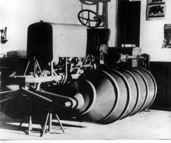
See that tractor "wheel"? That's what I'm trying to describe to you to manufacture and place in the larger pipe, letting the water flow around it, imparting spin. 
I'd make the fin run once around the pontoon from one end to the other though and not have such a "screw" look like in the picture. . . . . . Mac Nothing difficult is ever easy! Perhaps better stated in the words of Morgan Freeman, "Where there is no struggle, there is no progress!" Copeville, Texas |
||||
| Woodsworks Newbie Joined: 16/08/2010 Location: New ZealandPosts: 9 |
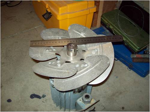
Here's a pic of the fan I want to use as an impeller. It is out of a refrigerated container, so anyone around the world wanting to try this should be able to find one, and for being made for a marine environment, it is corrosion-proof. To use as a kaplan runner, it will need a streamlined housing around the boss top and bottom, fitting just inside the inner edge of the blades - this deflects all the water flow onto the blades and will also help support the blades. Mac, while your fin-around-tube-inside-tube idea will work (just like the old towed ship's log) the relatively large surface area of the tube will reduce its efficiency. The kaplan uses exactly the same principle, just with more, shorter fins. I have measured the pitch of the fan (22.5 degrees), and I estimate that my fan might rotate at around 80RPM, allowing for 50% slip - it is just a simple calc, speed of flow through the net area of the fan (1m/sec), divided by the advance of the fan per rev (.36m/rev) x 0.5 (arbitrary fudge-factor). The amount of slip depends upon how heavily loaded the fan is - with no load, the slip will drop to practically nothing and the fan would spin at maybe 250RPM. Any engineering types out there feel free to point out any flaws in my logic, please? I can hardly wait for summer to get here so I can start building it without freezing to death - the creek is fed by a spring coming from the bowels of the earth, and is always about 10 degrees C Regards, Paul Woody of Whangas "To have never failed is to have never discovered the full extent of one's potential" |
||||
| Robb Senior Member Joined: 01/08/2007 Location: AustraliaPosts: 221 |
The density of water is much greater than air. If you have a worth wile head (enough to drive a F&P) that fan will be bent scrap metal in seconds  Think boat prop with strong thick blades and the outer section of the blade cut off. Note the streamlined shaft too. Think boat prop with strong thick blades and the outer section of the blade cut off. Note the streamlined shaft too.

|
||||
| MacGyver Guru Joined: 12/05/2009 Location: United StatesPosts: 1329 |
[Quote=Woodsworks] . . . the relatively large surface area of the tube will reduce its efficiency. I don't think you're going to get a heck of a lot of power out of this thing any way you do it, but if drag is a concern, make the inner, fluted tube more buoyant so it floats more on top of the water flow, with the escaping current turning against fairly deep fin(s) in the water. I'd make maybe 3 fins to wrap around the thing, so there was at least one full fin (between three total) in the water at one time. If your fan doesn't get bent to heck right out of the chute, I bet it catches weeds and stuff, whereas my design would let debris slip by. Of course, if the water from this spring is pristine, bottle it! You'd likely make enough selling it on to pay for mains electricity! 
. . . . . Mac Nothing difficult is ever easy! Perhaps better stated in the words of Morgan Freeman, "Where there is no struggle, there is no progress!" Copeville, Texas |
||||
| Woodsworks Newbie Joined: 16/08/2010 Location: New ZealandPosts: 9 |
Don't worry, I am quite prepared to write off the fan testing the concept. I've worked on designs for 200-tonne towing winches for deep-ocean tugboats that the operators kept bending/breaking....8-inch shaft: bent it lots....10-inch shaft: bent it quite a bit....12-inch shaft: didn't bend the shaft but tore the winch off the deck instead :D The fan blades are only 1.6mm alli so I'm not expecting much of them. It's no biggie if they bend downward, just so long as they don't break right off. The intake will have a grille to keep the flotsam out, angled to the flow so it will be self-clearing. It's amazing how much plant matter washes/blows into the creek. I just want something cheap and nasty at this stage to get an idea of how much power I might get. I don't need to fit an F&P motor straight away, I have a huge collection of largish stepper motors to choose from, which I can add one by one (Wow, variable load!). It may well turn out that this is all the turbine will run (especially if the blades bend over!). The next iteration, if it gets that far, will be a purpose-built runner with decent thick blades. Regards, Paul Woody of Whangas "To have never failed is to have never discovered the full extent of one's potential" |
||||
SSW_squall Senior Member Joined: 20/03/2010 Location: AustraliaPosts: 111 |
G'day woody, Couple of comments: I think i confidently state that the fan you've got there is not suitable, firstly the diameter is too big, secondly the blades are too shallow in pitch for there length and lastly it wouldn't be strong enough... The flow through this 10" - 12" sized kaplan machine would be in the order of 250L/s at a head of 1-2m. Strongly recommend you read this article, which is a good read: MICRO HYDRO ARTICLE Importantly this outlines the pitfalls and successes of a setting micro hydro rig. The machine featured is the Energy systems and designs low head machine, find it here: LOW HEAD MACHINE Also have a look at the FRENCH RIVER LAND website for there rebuild of a hydrolec tube turbine for info on a comercial scale unit If you check out the graph at approx 1m head it will be using about 35L/s and generating 150W. This machine has a 5" impeller so you can get a good idea of what sort of flow for the size of the machine concerned. Which would be about right for the hydro resource you have availiable Strongly suggest you consider one of these machines, otherwise you will pay in irriation, downtime and hassels with something that is less than serious. If it's just for experimentation value, on the other hand, then perhaps try trimming the blades down the reasonable diameter and by all means give it a go... Have fun in any case AB Einstein: Everything should be made as simple as possible, but not one bit simpler |
||||
| Woodsworks Newbie Joined: 16/08/2010 Location: New ZealandPosts: 9 |
Hi AB Having read through the articles and website thoroughly, and looked at the video linked from the homepower site, I wholeheartedly agree with you, I am on a hiding to nowhere with the fan impeller idea. I'm relieved to see how small the impeller is in the LH1000 turbine for the power it can turn out, and how simple the intake guide and draft tube is. The small size of the piping makes it a whole lot easier to build with off-the-shelf plastic piping components, but I am thinking 6" would be better, much more common. I might have to make up a wooden pattern and go see my mates at the foundry. An alli impeller that size would be a doddle for the local boat propeller manufacturers to cast. Thank you so much for posting the links, it has put me on the right track for sure. Regards, Paul Woody of Whangas "To have never failed is to have never discovered the full extent of one's potential" |
||||
| SSW_squall Senior Member Joined: 20/03/2010 Location: AustraliaPosts: 111 |
No worries mate, happy to offer my 2c... The boat propeller is definitly a better starting point, a couple more comments on this idea: Because the surface area of a circle varies with the square of the diameter the effect of 5" vs 6" may be more than you'd think at first glance. The difference between the area of the two circles (6^2 - 5^2)/5^2 (36-25)/25 = 0.44 44% increase in area!! Based on even this simplistic assesment your 6" machine could use 60-70L/s which is more than more stream has to offer! Which bring me to my next comment... Fixed pitch Kaplan machines have very poor part flow efficiency, that's why all comercial scale machines have variable pitch blades, to cope with variations in flow. Because variable pitch is really not easy to pull off, a fixed pitch micro kaplan machine must always run at full flow. Hence your 6" machine may work well when the water is available to run it but will give you very little or nothing otherwise. As Gordon has been at pains to point out in other threads a wind turbine that generate some power all the time is much better than one that delivers max power only a couple of days a year. If i were you i would go for a 4" impeller and try to maximise the available head. Because the pipes wont have to handle as much water they can be smaller and cheaper. So if you have to run your head race channel an extra 5m further to get another 0.5m of fall, by all means do so. Because your machine will be able to run all the time you'll get more energy on an average basis. Also efficiency wise i would guess that 4" machine running at 35L/s on a 2m head would make more energy than a 6" machine running at 70L/s on a 1m head. Regards AB Einstein: Everything should be made as simple as possible, but not one bit simpler |
||||
| Woodsworks Newbie Joined: 16/08/2010 Location: New ZealandPosts: 9 |
Hi AB. You say yourself in your post above that a kaplan copes with different flow rates by altering the blade pitch. This means that pipe diameter is less important than matching blade pitch to flow. Part of my reasoning for a larger pipe is so I can use a larger boss too. I flipped through an aluminium sections catalogue and found some heavy T-sections, just perfect for cutting down into short blades with a wide foot that can be bolted on and hence is adjustable. To make this work, however, a decent area is required to bolt the feet to, so the boss needs to be fairly large. I hate the idea of putting a whole lot of effort into building a runner and then finding that it barely works because the pitch doesn't match the flow. Okay, altering the pitch is still a major strip-down job, but at least it is able to be fine tuned. The only major issue I have right now is having to wait to buy a rotary table for my milling machine so I can machine the large circular recesses in the boss. Regards Paul Woody of Whangas "To have never failed is to have never discovered the full extent of one's potential" |
||||
| Jarbar Senior Member Joined: 03/02/2008 Location: AustraliaPosts: 225 |
Paul, reading through your postings and with you designing abilities it occurred to me that some of the aluminum windmill blade extrusion available on this site might be worth considering. The boss your considering could have flats milled on it the width of the blade.And be drilled to carry some 25mm aluminium shafts and the blade sections slid over them.They would allow easy angle and diameter changes which once established could be made more permanent by machining a diameter onto blade tips and fitting a captive ring. If you wanted to experiment I could send some PVC blade offcuts to try.I have no experience in this area other than knowing of the blade sections adjust ability. Edit I also remember a New Zealand manufacture Hamilton Jets which were a linear pump for boat propulsion.From memory they were about 150/200mm in diameter.Maybe one of these used in reverse could offer a solution.Many old ones would be around I imagine. Anthony. "Creativity is detirmined by the way you hold your tounge".My Father "Your generation will have to correct the problems made by mine".My Grandfather. |
||||
| Woodsworks Newbie Joined: 16/08/2010 Location: New ZealandPosts: 9 |
Hi Anthony That's a very kind offer, but the PVC profile is probably too large for what I have in mind. Here's a screenshot of what I have drawn up: 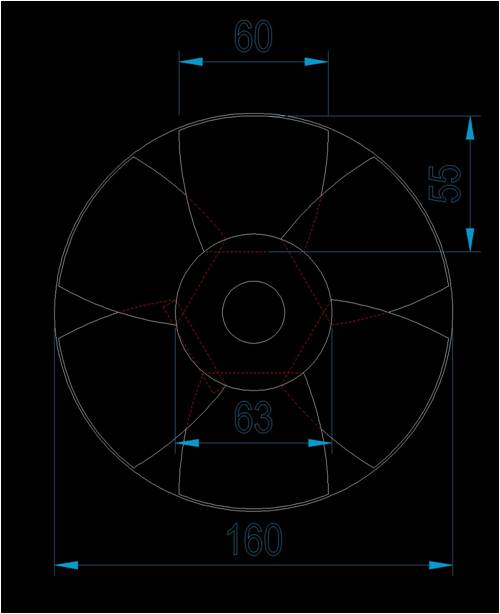
The T-section I am hoping to get is 60x60x6mm. Regards, Paul. Woody of Whangas "To have never failed is to have never discovered the full extent of one's potential" |
||||
Don B Senior Member Joined: 27/09/2008 Location: AustraliaPosts: 190 |
Hi Woodsworks I think that I made a similar suggestion on another earlier thread but, as an experiment, have you thought of trying the carcase of an outboard motor, less the engine, as a poor man's kaplan turbine? It has everything you need including propellor, right angle drive, step up gears, water seals, mounting bracket, etc. All that you have to do is attach your alternator in place of the engine. Oh yes, you would also need to install your pipe to direct as much water flow (and head) as you can gather into the turbine The only thing that you would need to remember is to set the propellor pointing upstream so that the lifting side of the prop blades are downstream. This is one of the essential differences between a propellor and a turbine. An outboard propellor (or a fan for that matter) is actually a far from ideal ideal turbine blade, but, if you get some encouraging results, you can then look into making a more effective turbine to replace the propellor. When I was living on a sail boat, I had an alternator driven off the propellor shaft, which I used when under sail. It didn't produce much power (although it could when driven by the engine) but it did make enough to run the auto-pilot and nav lights, and help a little to keep the frige cold. Again, the propellor was used very inefficiently as a kaplan turbine for this purpose (and had its lifting sides upstream), but, even so, it certainly delivered useful power. Regards Don B |
||||
| Frank Newbie Joined: 13/10/2010 Location: Posts: 5 |
Hi It's good to see someone else trying to make power from a creek with little fall and volume, my creek runs through our property for 400 metres with only about 1.2 metres of fall overall. I looked at and thought of many ways, including the outboard motor leg with propeller, and drew numerous diagrams, before settling on one. But it really comes down to using as much water as you can when its available. When it's raining there's less solar power for my panels, but more power from extra creek flow. Thats why I decided on a undershot wheel. I have a loose sand and stone creek bottom, to tie my race walls in place I drove star pickets in then boxed and poured footings, laid blocks and cour-filled them. The walls against the dirt/sand creek bank stops the bank from eroding. The other wall helps direct water to the wheel. Between them is a aluminium floor which reduces turblance and speeds up flow. Look up Franks undershot wheel for photos. Contact me if you need any more info, Frank. |
||||
| VK4AYQ Guru Joined: 02/12/2009 Location: AustraliaPosts: 2539 |
Hi Frank My grandfather was a bit of an innovator for his time, he died 60 years ago at age 83 to give you an idea on the time frame. He made a undershot wheel on the creek like yours, and it powered the house and pumped water to the garden and the dairy. It was 8 ft in diameter and 3 ft wide the race depth was 1 foot and from memory about 200 yards long for a fall of 3+ foot. It ran for years even after he died , but was washed away in a flood in 1998, It wasn't used for electricity anymore but pumped water for the house, dairy, pig pens garden and orchard. Most of the race was timber as he had a sawmill with a big cast concrete base for the wheel and end of the race. The whole wheel was wood construction as he had plenty and reinforced with steel ties he made in his blacksmith shop, the main shaft was a piece of 3" shaft running in wood bearings with ring oiler for lubrication. A mill like that could be replicated all along the creek and supply the power needs of all the people along the creek without interfering with the environment or causing any pollution. The cheap at the time rural power grid killed a lot of out little projects bu the time is coming when all these things will be back in vogue again, so keep up the good work, I wish I had a little stream running through my place. All the best Bob Foolin Around |
||||
| Page 1 of 2 |
|||||
| The Back Shed's forum code is written, and hosted, in Australia. | © JAQ Software 2026 |
