
|
|
Forum Index : Other Stuff : Diesel DC Gen
| Author | Message | ||||
| Disco Stu Newbie Joined: 13/12/2009 Location: Posts: 16 |
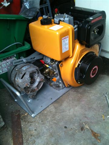
thought this mite up you guys alley been planning on making one of these for a long time ended up doing a cashie for the neighbour wiring a VN commodore engine into a toyota, and he made up the mounting bracket and machined the pulleys and supplied a engine (great deeal!!) a little chinese diesel engine and an old scavenged leece neville altrnator 12v 160A and a mulit rib belt to spin it all, any way thats the mechanical bit out of the way now to make it interesting... planning on making it auto start ie switched on and off be the pl40 g terminal via a relay, am going to use a picaxe 28m to control it all including cranking, throttle, fuel solnoid and alternator field control. will keep you updated as i progress and will hopefully pick some of you guys clever brains for some programming help cheers stu |
||||
| VK4AYQ Guru Joined: 02/12/2009 Location: AustraliaPosts: 2539 |
Hi Stu Great bit of gear mate but it will need rubber mounts as these little buggers vibrate something fierce, it will walk out the door of the shed otherwise. What voltage is it doing as it looks like the regulator is not there? All the best Bob Foolin Around |
||||
| Disco Stu Newbie Joined: 13/12/2009 Location: Posts: 16 |
heres the old throttle lever 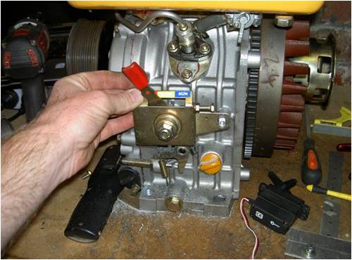
and the servo bracket 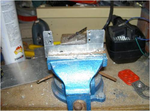
fitting pickup for RPM (yes its a bit rough!!!) 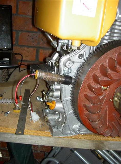
and all fitted up using debug to test servo positions, and theres not much movement to get it from stop to full throttle thats why i added the rough looking extension tot he throttle 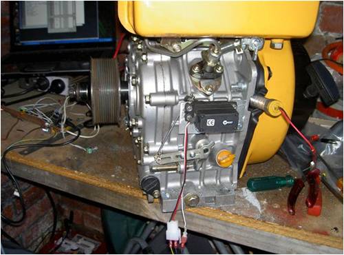
just ned some foam rubber to mould around the pickup to block it off nicely cheers stu |
||||
| Disco Stu Newbie Joined: 13/12/2009 Location: Posts: 16 |
hi bob yeah rubber feet is on the to-do list as it does jump alot will see how the throttle servo fares?? was a 12 volt unit but field will be controled by picaxe hopefully as the factory unit is non adjustable if i cant get it to work from the picaxe i will use an adjustable external regulator cheers stu |
||||
| VK4AYQ Guru Joined: 02/12/2009 Location: AustraliaPosts: 2539 |
Hi Stu Sounds good mate, they do vibrate a lot so may be wise to mount delicate parts remote. I fix a few of these on little gen sets and most damage is things fallen to bits by vibration. Will be interesting to see if the PIC works on the regulator. All the best Bob Foolin Around |
||||
| Gizmo Admin Group Joined: 05/06/2004 Location: AustraliaPosts: 5186 |
Hi Stu Yeah this is a great project. Programming the software will be interesting. When I worked for Telecom one of my jobs was testing the diesel generators. We would cut the main power and let it go through its automatic startup routing. When there was a power outage, the genset would wait for a few minutes, then try to start 3 times, each attempt about 1 minute apart. If it didn't start after the 3rd attempt, it would send an alarm signal to Brisbane, and they would call out a local staff member to visit the site and work out whats wrong. If it did start, it would still notify Brisbane to let them know, and they would notify the local staff next work shift. Once power was restored, the genset would continue running for a several minutes, just in case the power dropped out again. They were pretty reliable units, and loud! I dont remember the capacity, but I would imagine over 25kw. Glenn The best time to plant a tree was twenty years ago, the second best time is right now. JAQ |
||||
Downwind Guru Joined: 09/09/2009 Location: AustraliaPosts: 2333 |
At least without a regulator fitted you have got yourself a welder if you run it with the fields connected to 12 volt. (although the higher voltage may blow the diodes) For what purpose do you want to control the charging with a picaxe? I would think using the original voltage regulator for the alt would have been the best choice. It will be a handy little DC generator when done, i have built a few over the years and the last one was with a electric motor, its great when you find you have a flat battery and with 10 minutes running you can start a car. Its a hell of a lot better than waiting for hours with a 4 amp charger and easier than trying to get a jump start. Pete. Sometimes it just works |
||||
| Disco Stu Newbie Joined: 13/12/2009 Location: Posts: 16 |
hmm must be some timing issues up there my reply to bob appears before his post... glen, yea there are some great little control panels around (deep sea, murhpy, and the latest ive come across the intellidrive) we work on these all the time, on pumps and gensets as well none with remote comms yet though although i imagine they are out there, im planning on the same sequence for starting, although fail to start will activate a warning alarm/strobe. hmmm i have a nextg modem in my ute though but will get it runnning first. electrics are pretty easy but im new to electronics and have been mucking around with the picaxe for 6 months or so but need something interesting to motivate me to get into it, will see how i go here will get the auto start and throttle control sorted first. may have bitten off more than i can chew pete, the plan is to have the picaxe monitoring the battery voltage and regulating the engine speed first then the alt field second so when the batterys get full and voltage is easier to maintain it will reduce engine speed and fuel usage and then once the speed is down low enough and still needs to be regulated it will reduce field current. this will allow for intermittent heavy inverter loads too and will ramp up the speed again once heavy load is applied. the original reg in the alternator is set at 14.2 i like 14.6-14.8 for batt charging (flooded batterys) as it pumps in the juice a bit faster anyway stripped the alternator today and blasted it ready for some paint tomorrow when i get a spare 5 mins at work, bearings are in good nick so is just getting dulux rebuild.. cheers stu |
||||
| Downwind Guru Joined: 09/09/2009 Location: AustraliaPosts: 2333 |
What/how is the servo for the throttle controlled, pulses, analog (voltage) or what? As just thinking about how this can be done under picaxe control. Most alternator voltage regs from my understanding work by switching on and off the field windings, and i also question the speed a picaxe can respond to this. Just thinking ahead of you. Pete. Sometimes it just works |
||||
| Disco Stu Newbie Joined: 13/12/2009 Location: Posts: 16 |
hi pete bit confused with the first question, was going to use 12v fed into the picaxe via voltage divider and then this will be used to work out the point where the servo will be set via the servopos comand, have yet to be working out any programming code yet. yeah that might be a point getting the picaxe to react fast enough to control the voltage will see how we go and if it isnt good enough can fall back to a regulator cheers stu |
||||
| Downwind Guru Joined: 09/09/2009 Location: AustraliaPosts: 2333 |
Ok so its just a big servo you are using and not some tricky motor or the likes. I see the X2 chips will allow servo operation up to 32 meg and would be the better way to go i think. Thinking about the Vreg and see no real point in picaxe control as engine revs will give good overall control. As for the higher voltage out with using the standard vreg i think it would be easy to trick the reg for a increased ouput voltage. A simple diode in the sense line should give a 0.6 volt increase in output. The rest of the program should be easy as the servo only needs a value between 75 and 255 for full control. This is easy to obtain by a ADC reading of battery voltage and a few lines of program. Watching with interest. Pete. Sometimes it just works |
||||
| Disco Stu Newbie Joined: 13/12/2009 Location: Posts: 16 |
morning people well i finally got to do a bit more work on my project over the last few days, been a bit busy with site work and have just got a new job flying out tuesday so have had a bit of time up my sleve 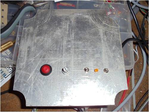
this is my little dash panel (so far) its going into a fibox enclosure with a clear openable lid on the left the start button, the pot for controling the throttle or field strength, next the switch to select throttle or field strength mode, then a power/fault LED and then run/shut down switch which enables the start button and throttle, when switched off it will set the servo position to close the fuel rack. 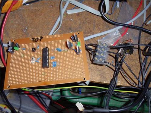
this is my pigs breakfast  well it is at the moment while programming and building up, top left is the 5v reg top right 6v reg for servo, then below are 2 mosfets one for the start relay and the other for pwming the alternator field. have a little connector strip for connecting and disconnecting leads to the engine, this is vry handy as you have to disconnect the servo when programming or sometimed the servo will jump around and cause a spike and stuff up the download. well it is at the moment while programming and building up, top left is the 5v reg top right 6v reg for servo, then below are 2 mosfets one for the start relay and the other for pwming the alternator field. have a little connector strip for connecting and disconnecting leads to the engine, this is vry handy as you have to disconnect the servo when programming or sometimed the servo will jump around and cause a spike and stuff up the download.
have had a few close calls, first one wad dumb hooked in the diode protected relay in the wrong way and blew a track, the mosfet and a 5v reg, noticed the picaxe getting warm. so shut it down and found 12v at the 5v rail replaced the parts and repaired the track and tried the picaxe and it still worked  . i keep a spare anyway cos im a nnubie and am gonna do that stuff anyway. . i keep a spare anyway cos im a nnubie and am gonna do that stuff anyway.
so far spent about 8-10 hours on the picaxe side, slowly adding parts and then coding them in to work can only do about 3 hours in a stint or i get a brain ache, too much thinking im not used to it!! previously have only done the little tutorial projects ie: led flasher and servo connected to a pot, great learning curve for me nothing like being thrown in the deep end. could have gone out and bought or aqquired an auto start controller but then what would have i learnt from that?? cherio stu |
||||
| The Back Shed's forum code is written, and hosted, in Australia. | © JAQ Software 2026 |
