
|
|
Forum Index : Other Stuff : Home Built CNC Project
| Page 1 of 4 |
|||||
| Author | Message | ||||
Bryan1 Guru Joined: 22/02/2006 Location: AustraliaPosts: 2155 |
Part 1 Hi Guy's, Well finally got around to taking some pic's of the cnc. She's about 95% finished and the x and y axis's are working nicely and calibrated to under 0.001" This is a rear view of it, the bed is some 20mm resin bond fiber board which is used in the electrial industry for high voltage boards. I scored a 600x1200 length for free. 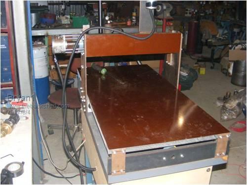
This is a front view and I do need to source some 20mm angle to install of the front of the sides of the Y-axis to brace it up 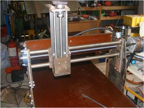
This is the X-axis motor setup 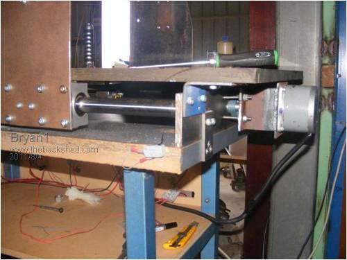
This shows the x-axis setup 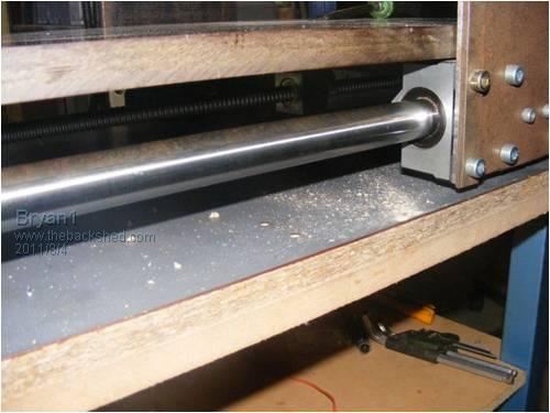
This shows the Y-axis motor setup 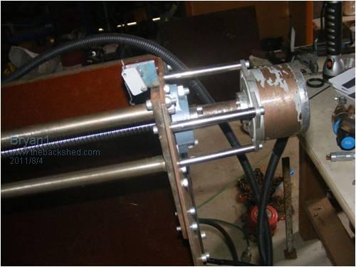
The Y-axis head unit is made from a block of cast iron and I bored 2 holes to suit oil light bushs, the rails are 3/4" 4140 round bar and when setup there is less than 0.001" deflection. 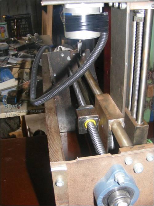
Run Of picture space so the next post will detail more. |
||||
| Bryan1 Guru Joined: 22/02/2006 Location: AustraliaPosts: 2155 |
Part 2 This is the Z-axis which I made from scratch. The lead screw is a 12 tpi acme thread I cut in my toolroom lathe and I have an acme tap to suit. The thread is very little to no backlash. The 2 guide bars are 10mm rods taken from an old printer so they are good hardened rods. The cutter head block is also cast iron and I tapped 4 off 6mm holes so the cutter head can attach. 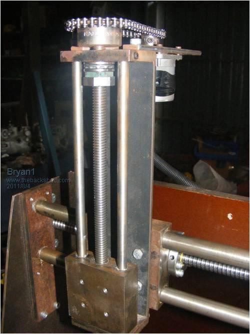
This pic shows the 3 seperate 3 amp constant current circuits, one for each axis. The veroboard one was given to me by the guys at the Adelaide Uni and I made circuit boards for the other 2. They work very well and I reckon 3 amps is more than enough current for the steppers I'm using. 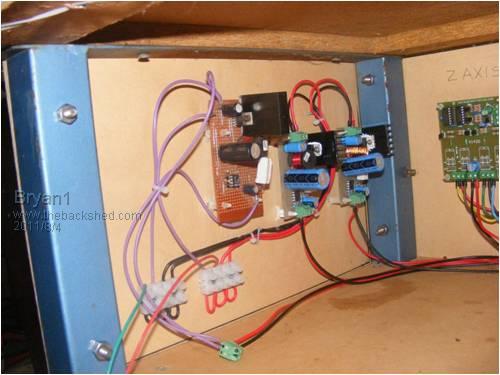
This the control section with 3 off of the Oatley controllers and the parallel input board I made my self ages ago for early testing. 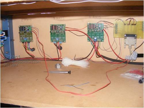
For ages I played around with acme screws then all thread but gave up in the end and bought ball screws for the X and Y axis's. It was the best move I made as they run silky smooth even single stepping. With a 5mm lead they will really suit a micro stepping setup and I will get working on them pretty soon. For now I'm goingto setup my dremmel tool and just use the holder off the dremmel drill base to get me going. All in all this is around 4 years work off an on and if I didn't break my finger and have the time off this project would still of been 6 months away. The first job will be machining a grid pattern on the fibre board base and drilling some M6 holes 18mm deep so not to break thru to be used for holding down jobs. I still need to instal the limit switch's and make up the main control board with the power switich's and the E stop. Cheers Bryan |
||||
| Gizmo Admin Group Joined: 05/06/2004 Location: AustraliaPosts: 5186 |
Nice work Bryan I havn't used ball screws on my own CNC but have worked on a few machines that use them. Keep the grease up to them and they last decades. Glenn The best time to plant a tree was twenty years ago, the second best time is right now. JAQ |
||||
wdyasq Newbie Joined: 29/07/2008 Location: United StatesPosts: 21 |
Looks good Bryan, Mill on.... Ron Brown Adventure is just bad planning." -- Roald Amundsen |
||||
| vasi Guru Joined: 23/03/2007 Location: RomaniaPosts: 1697 |
Nice setup Bryan! To see it in action, I understand we have to wait a little. Vasi Hobbit name: Togo Toadfoot of Frogmorton Elvish name: Mablung Miriel Beyound Arduino Lang |
||||
| Bryan1 Guru Joined: 22/02/2006 Location: AustraliaPosts: 2155 |
G'day Guy's, O'well back to the drawing board on the Z-axis as the stepper is toast. I used my stepper tester circuit to make sure I had the wiring right. Tested another controller still no go. Tested another another power supply, still no go. Tried a direct power supply and got the smoke. Anyway that stepper was out of an old printer and my single stepper circuit did do it but looks like I'll have to replace with a 5 volt 1 amp bi polar stepper I have here. so a new circuit will need to be made to suit the bipolar and I do have a few chips here to do it. Cheers Bryan |
||||
| Tinker Guru Joined: 07/11/2007 Location: AustraliaPosts: 1904 |
That's quite some machine you are building there Bryan. I can see an awful lot of work that went into it so far. So, what's a little set back  with a smoked motor? with a smoked motor?
More fun, of course  Klaus |
||||
| Bryan1 Guru Joined: 22/02/2006 Location: AustraliaPosts: 2155 |
G'day Guy's, I pulled apart the z-axis stepper today to see what was wrong and 2 of the main pad's were cut so I soldered on a bit of wire and tested it. No movement from the shaft but one could feel the ramp up and sudden stop. Pulled it apart again and had a closer look and one of the winding had burnt out, tried to solder it but on the next test still didn't work. Anyway I have 4off of those 16mm split bearings so I'm going to make a new Z-axis complete using the 16mm bearings and rod's and I do have a 5 volt 1 amp bipolar stepper motor I'll use as the drive. As I will need to make a new driver board I'm going to make up some A3977 boards so I can go the micro stepping route. The only set back is I need to source some 3 watt 0.2 ohm smd resistors for the circuit design I have here. I do have a transparency so as most of it is smd it will be a fun job to make with only one good hand. Hopefully on Tuesday the cast will come off an I will have more use of my right hand but looking at the dressing before the wound has weeped again so I reckon the 20 or so stitch's won't come out on Tuesday. This cnc has been a long term project and with going the ball screws on both the X and Y axis I might have to have another look on fleabay and get a ball screw for the z-axis. Then the cnc will be totally driven by ball screws and accuracy won't be a problem. Like I've said once this small cnc is done I aim to start on the big one and when my tax return comes in I'm buying the RHS to make the frame. As I already have the steppers for the big one I will need to find a new driver circuit as they all are rated at 250 volt, the X and Y are rated at 11 amps and the Z is rated at 7 amps. In order to get the full capacity of these 8 wire steppers homebrew micro stepping circuits are hard to come by so if any guys have a link or such and can provide details I will appreciate it. Cheers Bryan |
||||
| Bryan1 Guru Joined: 22/02/2006 Location: AustraliaPosts: 2155 |
G'day Guy's, Well I did make a new Z axis but found using just single linear bearings they was a bit of slop on the cutter so decide to grab 4 16mm linear bearings off ebay and make a whole new Z axis. In order to hold the ball screw nut I machined up 2 identical steel blanks to sit on the inner of the linear bearing holder then tapped a hole in each to hold the nut. A 6mm ali plate holds each pair together and a 15mm plate hold the DC motor spindle. 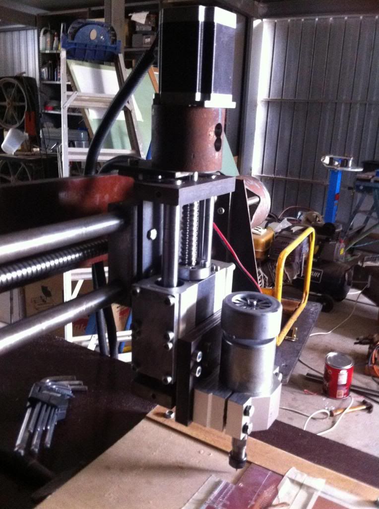
Now to test out the CNC I put some pcb on the bed and did a few trial runs to get the right depth. Decided to finish the pcb design of the arduino LCD board so I can use it on the DM. Anyway I've been using Sprint Layout for years to do pcb design and feel it is great for PCB design BUT NO BLOODY GOOD for gerber export. I used that scrap piece to do a dummy run to ensure the Gcode was right only to find on cutting the pads they were cut alround and when a track was cut EVERY BEND was cut individual. So back to Sprint Layout and try using the 'connections' button so every pad and track were identified. 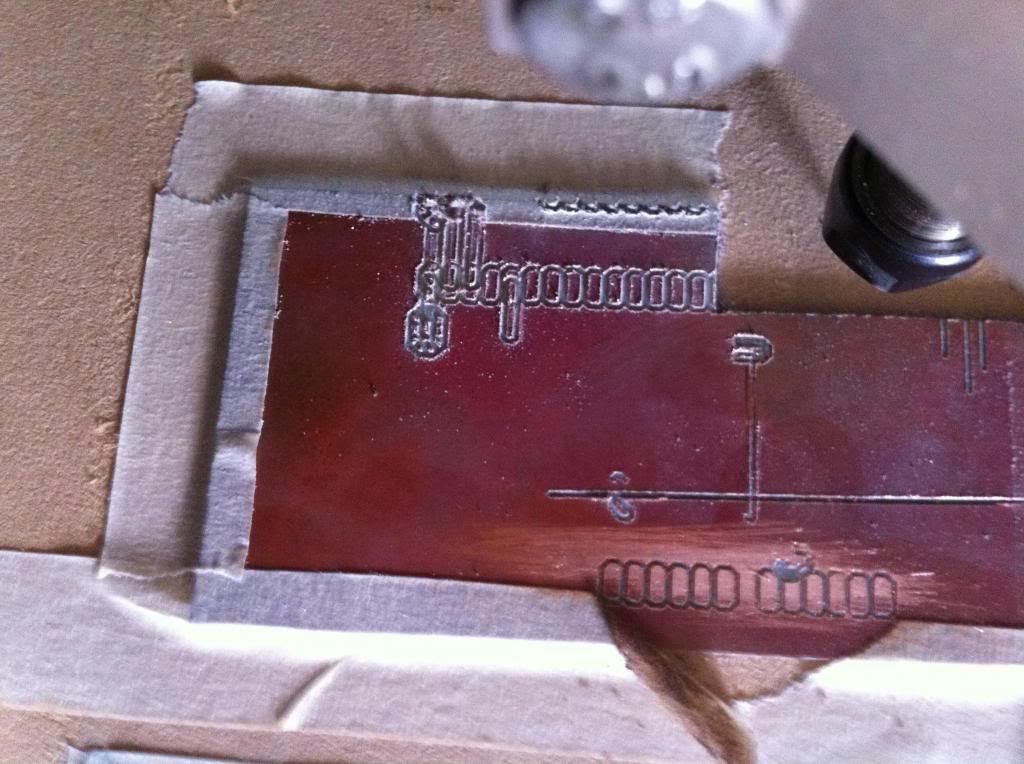
Nope that didn't work and the crap in the middle was the result. So after watching nearly 2 hours of dave's EEVblog on Kicad I downloaded that to try. What a nightmare to try and use so next stop will be designspark and see if that is a tad easier to use. Regards Bryan |
||||
| Gizmo Admin Group Joined: 05/06/2004 Location: AustraliaPosts: 5186 |
Ah the fun of fine tuning. Building the CNC table is the easy bit, its the getting it to work properly that takes the effort. But it will get there. My own table is now a valuable part of my workshop, and I use it regularly, but it took a long time to get it where it is now. Bryan your shed looks like my shed, crap everywhere. Glenn The best time to plant a tree was twenty years ago, the second best time is right now. JAQ |
||||
| Bryan1 Guru Joined: 22/02/2006 Location: AustraliaPosts: 2155 |
G'day Glenn, Yea mate the shed is getting a cleanup albeit slowly as too many jobbies get in the way  Anyway went back up to the shed after dinner last night and tried a few other things. One thing I found with isolation milling using Sprint Layout one needs to export the file in HPGL format. Now the fun part of that is although all the settings are in metric in Sprint Layout the output comes out to imperial. Mach3 will convert the HPGL file then I open the file in Kcam to convert it over to metric. The trials I did last night showed YEA it will work but one needs to ensure the spacing between tracks is wide enough. for cutters I'm using broken carbide drill shanks and for now just freehand grinding them on a silicon carbide grinding wheel, that Quorn tool and cutter grinder I got partly finished is back on the bench and I'm nearly there to get it working so that will be used to make and sharpen cutters for the cnc. Anyway went back up to the shed after dinner last night and tried a few other things. One thing I found with isolation milling using Sprint Layout one needs to export the file in HPGL format. Now the fun part of that is although all the settings are in metric in Sprint Layout the output comes out to imperial. Mach3 will convert the HPGL file then I open the file in Kcam to convert it over to metric. The trials I did last night showed YEA it will work but one needs to ensure the spacing between tracks is wide enough. for cutters I'm using broken carbide drill shanks and for now just freehand grinding them on a silicon carbide grinding wheel, that Quorn tool and cutter grinder I got partly finished is back on the bench and I'm nearly there to get it working so that will be used to make and sharpen cutters for the cnc.
Regards Bryan |
||||
| vasi Guru Joined: 23/03/2007 Location: RomaniaPosts: 1697 |
Bryan, take your time to read this page (now, that you have problems with the generated g-code), is a must. http://reprap.org/wiki/PCB_Milling Considering that you like to work directly in a PCB Layout program (I guess some day you will make a mistake and you will start to appreciate also a schematic editor for all the nets it provide), maybe gEDA PCB is perfect for you. http://www.delorie.com/pcb/geda-windows/ The "buildyourcnc.com" guy recommends Eagle and a plugin for routing your pcbs http://buildyourcnc.com/PCBIsolationRouting.aspx BTW, this guy is fantastic for his pick and place machine! http://buildyourcnc.com/PickandPlaceMachineTheredFrog.aspx Hobbit name: Togo Toadfoot of Frogmorton Elvish name: Mablung Miriel Beyound Arduino Lang |
||||
| Bryan1 Guru Joined: 22/02/2006 Location: AustraliaPosts: 2155 |
Hi Vasi, Thanks for those links and I had a good read this morning and my final goal is to get this cnc running on EMC2. But until I get the cnc totally finished and my new electronics room in the new shed setup the cnc will stay in my shed. But I can't get the net in the shed so running ubuntu and getting everything without a net connection would be impossible. Anyway today I redid the HPGL output and designed up a new board for our fridge as that is one project I need to get going on. Anyway honed up the tool with a diamond board and got the pcb design converted over to G-code. I did find in the G-code it would come up to a drill point then the Z would just go up and down twice. No problem so put a pcb board on the bed, secured it with 1" masking tape then ran the dial test gauge over the surface to find it was within 0.1mm. Anyway cool got it running and apart from one track that was cut too thin the board was coming out nicely. Then with say about 10 minute to go the cnc stopped moving but the code in Mach3 was still running. My dog came in the shed and pulled the ground out (not knowing) and that was it one scrap board. O'well ol' murphy did say 'leave something to wreck ya day and I'll find it'. well today it did bite me on the bum so time to get all the limit switch's on and get the heatsink/fans on the steppers. Also need to put a pair of fans on the heatsink of the 3 axis controller as that get pretty hot. So today milling out that board the way it did I reckon it is in good working shape so now I'm on the next path and thats learning the in's & out's of it and getting some goodies made. Regards Bryan |
||||
| brucedownunder2 Guru Joined: 14/09/2005 Location: AustraliaPosts: 1548 |
Good one Bryan . You have certainly been busy ,like members that "do things" ,good for you . I've been thinking of how you were getting on with that cnc, knowing that you have been busy with real work this year. I'll be one of your customers,thats for sure !. Bruce Bushboy |
||||
| Bryan1 Guru Joined: 22/02/2006 Location: AustraliaPosts: 2155 |
G'day Guy's, Well the new 3 axis controller, engraving cutters and 1/4" collet finally arrived so got back into the cnc this week and had a bit of fun. Searching thru my dad's router collection I found a heap of bits that will be handy and I used a 19mm router bit to machine the table flat as it has a 2mm twist in the board. I spent a heap of time reading as it has been ages and learning how to do a sub routine and finally got some code done for milling the surface. Z-0.2 ' set the depth for new run X600 ' X travel M98 P0123 ' call sub O0123 G91 Y15 ' increment the Y axis G90 X0 ' back to global M99 At the end of the run I manually take the Y axis back to 0 and clean up the Y axis edge. Had the cnc running at 600mm/min and only taking 0.2mm cuts as that board is so hard. Got a bit late last night so today I'll finish the table surfacing and take a pic or 2. Man trying to relearn G-code after a few years does tax the grey matter but I am getting there and next on the list will be learning the can cycle so I can drill holes for clamping. Cheers Bryan |
||||
Downwind Guru Joined: 09/09/2009 Location: AustraliaPosts: 2333 |
Would a example help? G81 is the can drilling G-code command. In the fist line of code below G81 sets the drilling cycle for all lines to follow until a different G-code command is used, X&Y are just the start locations for the first hole, Z is the depth of the hole below zero setting, R is the "retract" height the tool will return to between holes when travelling, F is the feed rate in mm/min The code example will drill a line of holes at 25mm apart N11 G81 X0.0000 Y0.0000 Z-1.6000 R5.0000 F600.00
N12 X25.00 N13 X50.00 N14 X75.00 N15 X100.00 N16 X125.00 N17 X150.00 N18 X175.00 N19 X200.00 N20 X225.00 N21 X250.00 N22 Y25.00 X250.00 Here is a list of all G-codes incase you dont have them. G and M-code reference
Rev 1.84-A2 10-15 Using Mach3Mill the command prototypes not explicitly described as optional are required. It is an error if a required item is omitted. Summary of G-codes G0 Rapid positioning G1 Linear interpolation G2 Clockwise circular/helical interpolation G3 Counterclockwise circular/Helical interpolation G4 Dwell G10 Coordinate system origin setting G12 Clockwise circular pocket G13 Counterclockwise circular pocket G15/G16 Polar Coordinate moves in G0 and G1 G17 XY Plane select G18 XZ plane select G19 YZ plane select G20/G21 Inch/Millimetre unit G28 Return home G28.1 Reference axes G30 Return home G31 Straight probe G40 Cancel cutter radius compensation G41/G42 Start cutter radius compensation left/right G43 Apply tool length offset (plus) G49 Cancel tool length offset G50 Reset all scale factors to 1.0 G51 Set axis data input scale factors G52 Temporary coordinate system offsets G53 Move in absolute machine coordinate system G54 Use fixture offset 1 G55 Use fixture offset 2 G56 Use fixture offset 3 G57 Use fixture offset 4 G58 Use fixture offset 5 G59 Use fixture offset 6 / use general fixture number G61/G64 Exact stop/Constant Velocity mode G68/G69 Rotate program coordinate system G70/G71 Inch/Millimetre unit G73 Canned cycle - peck drilling G80 Cancel motion mode (including canned cycles) G81 Canned cycle - drilling G82 Canned cycle - drilling with dwell G83 Canned cycle - peck drilling G84 Canned cycle - right hand rigid tapping G85/G86/G 88/G89 Canned cycle - boring G90 Absolute distance mode G91 Incremental distance mode G92 Offset coordinates and set parameters G92.x Cancel G92 etc. G93 Inverse time feed mode G94 Feed per minute mode G95 Feed per rev mode G98 Initial level return after canned cycles G99 R-point level return after canned cycles Figure 10.4 - Table of G codes Sometimes it just works |
||||
| Bryan1 Guru Joined: 22/02/2006 Location: AustraliaPosts: 2155 |
G'day Guy's, Finally got the table machined up using that code above and tweaking it as needed. I endup doing the last 2 two runs on roughing over 2 pass's then took some reading with the dial gauge and wasn't happy 0.05mm out global. So went and opened the new box of router bits and grabbed the 19mm cutter so I had a new cutter to use. Set the Z -0.1mm and gave it a run over twice and got the needle hardly moving on the dial gauge so I'm wrapped that was done (do need to make a vacuum for the waste). For now I'm just going to set up the limits and use them for the home switch as now I've got the bed done the cnc does need to know where 0,0 is. I'll go active low like I did with with the E-Stop and use a separate ground so the parallel port doesn't show any magic smoke. ( Note to Shaun keep an eye on ya brother or no whiskey). Also I have to make a hole on the table underneath so I can grease the X axis bearing as grease and freeze spray didn't totally stop the creak as the X axis traveled. I am thinking long term the X axis is going to need to be upgraded to a 25mm ball screw as the 16mm maynot be upto the length. Still yet to find a decent G'code Editor as notepad won't cut it on some things I want to make. Anyway as it's Sunday, cnc is parked and time to sit back as the next week will be a busy one. Cheers Bryan |
||||
yahoo2 Guru Joined: 05/04/2011 Location: AustraliaPosts: 1166 |
I have had a reminder stuck on my computer desktop to try notepad++ with the G-code syntax highlighter add-on installed for a while now, https://github.com/robEllenberg/gcode-syntax I have looked at the .xml file and there is not much in it, so I am not sure exactly what the benefit of it would be. Definitely no mouse roll-over definition popups like I need to remind me constantly of code functions. I'm confused, no wait... maybe I'm not... |
||||
| Bryan1 Guru Joined: 22/02/2006 Location: AustraliaPosts: 2155 |
G'day Guy's, Well with my cnc up and running now I'm having a fun(NOT) time trying to find some software to design stuff for it. So if you guys have any idea on what would be the best to use any advise would be great. Cheers Bryan |
||||
| Gizmo Admin Group Joined: 05/06/2004 Location: AustraliaPosts: 5186 |
Bryan I use a few different programs, depending if I'm doing 2.5d or true 3d routing. For the 2.5d, which is pretty well 99.9% of the stuff I do, I use a program called Axis Motion. It's no longer supported or available, and a bit old now, and basic, with lots of keyboard shortcuts. But once you get the hang of it, its very fast to use, and creates very clean DXF files. Axis Motion was written by a laser cutter manufacturer. I then use CAMBAN to create the G-Code file. The free edition (0.81? ) has the basic functions like engrave, pocket, etc. Glenn The best time to plant a tree was twenty years ago, the second best time is right now. JAQ |
||||
| Page 1 of 4 |
|||||
| The Back Shed's forum code is written, and hosted, in Australia. | © JAQ Software 2026 |
