
|
|
Forum Index : Other Stuff : Effects Capacitors my Hydro
| Author | Message | ||||
herbnz Senior Member Joined: 18/02/2007 Location: New ZealandPosts: 258 |
After testiing capacitors on FP See windmill forum Doubling output. I could see that caps can be used to simulate extra windings. Now as caps change effect at differnr frequencies ie higher frequences they draw more current. One safe guard I built into my Hydros is a means of shorting the AC side in event load loss. I could see a unit tunned in with caps would draw more current in caps if load is lost. My small hydro is fitted with what is equivalent to a 80p (8 turns per coil )at present on a small jet giving 3 Amps to my batteries. It has been tunned to near optimine 900rpm . I remove load speed up to 1800 rpm dc volts 35v. then reconnected load. On connecting 3 Phase Caps 210 mfd total, current dropped to 1.5 a rpm down 400rpm I stopped unit wound rotor out until i again got my 3a rpm back 900 rpm. Again removed load speed went to 1200 rpm dc volts 42 v. So braking theory works but increase in volts not what i really want the main reason i put protection in incase a battery connection fails and equipment connected gets over voltage. Whats happening is the caps and inductance off load are a series load at or near resonance so each has high currents and voltages . now also on checking the wheel after I could see evidence of spinning on shaft although still tight (friction drive ) I believe that a similar effect went in to what happens if we over correct power factor on a AC motor on slowing down motor acts as a generator when Xl = Xc resonance and violent braking can shear the shafts of the motor. Herb |
||||
Steve9R Regular Member Joined: 24/01/2006 Location: AustraliaPosts: 72 |
Hey herb.. interesting. Ive also read through all the posts relating to adding caps to F&Ps.. I also run a water wheel, although unfortunately have 0 head.. if you get a chance would you mind posting a few pics of yours ? and some detail on the output / rpm you're getting from your 80p ? Personally i run a 3m diametre steel wheel, with a 33:1 gearbox driving a 7p3p80 over 180m of 35mm underground cable to my 24v battery bank.. Im finding that the most i can get out of the wheel is 2A .. so im always interested in methods of increasing my output.. (eg caps).. Steve |
||||
Gill Senior Member Joined: 11/11/2006 Location: AustraliaPosts: 669 |
Steve, Talking about a few pics and some details, how about you post a few of your own water wheel please? You don't seem to be getting much power out for a 3m wheel, though you could really be doing well I guess if flow rates are particularly low. 180m is a fair run for 24v. In earlier days when assessing my site for micro hydro, one location had the generator 300m from my camp. I considered running F&P unmodified giving 3 phase Hi V for the 300m run, feeding into a dual hub arrangment. The input going into one, an unmodified slave F&P running as a motor, turning the shaft to which the second ran as a 12v generator, and so feeding the battery. A simple low-tech, low cost approach, and I always kind of wonder how well it would have worked. was working fine... til the smoke got out. Cheers Gill _Cairns, FNQ |
||||
| Steve9R Regular Member Joined: 24/01/2006 Location: AustraliaPosts: 72 |
yeah that would have been ok, except ive only got 2 x 35mm cables in the ground.. so cant run 3phase up the hill.. Here's a pic for you.. taken in december after 35mm of rain.. so the creek is really flowing.. this is probably as high as it gets.. that sandbag wall is 4 x sandbags high.. I know.. i have to redo my channeling system, but its in quite a difficult position as the creek winds around a lot, and its difficult to funnel water.. 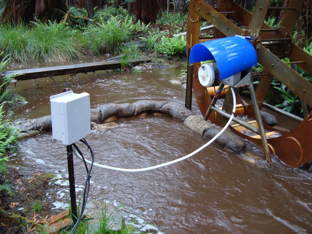
Steve |
||||
| herbnz Senior Member Joined: 18/02/2007 Location: New ZealandPosts: 258 |
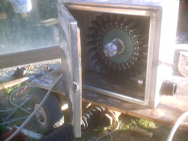
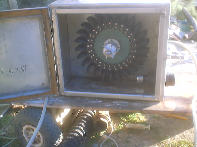
Hi Steve The use of caps on this topic was a side line to testing the effects of caps in my test bed. From this research i can say with confidence that they merely change the characteristics, you will only get gains if not correctly set to optimium rpm luckly in hydro's there is only one optimium speed unlike the variable windmills. Do you know the trick to wind the rotor out effectively weakening the field and allow more rpm ? I use this as a means to detemine optimium. ie if output goes up with speed increase I reduce turns / pole and visa versa . Re my set up I have Three hydro's and even then change to other units when like now we are in a drought, Smart drives when plenty water and the older gentle annies when i have to get efficient. I also manufacture units for neighbours etc a sort hobby business. I will include some photos of units. 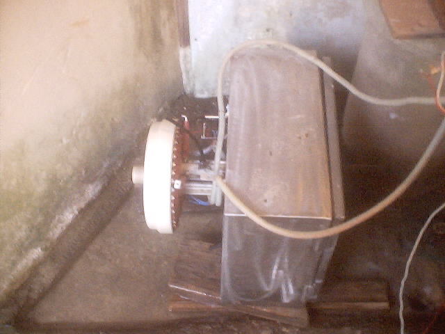
 |
||||
| Steve9R Regular Member Joined: 24/01/2006 Location: AustraliaPosts: 72 |
ahh you're doing turgo turbines .. I thought you said you had a water wheel! ;) the problem ive found with winding out the hub is yes you get more RPM, but less current.. so it sort of defeats the purpose.. yes in drought times like now, my wheel isnt even spinning though.. there's hardly a trickle through the creek, even the lobsters are hunting for deeper water! (one living under the wheel).. what sort of head do you have for the turgos? are you buying your spoons direct from ecoinn as well ? or sourcing them elsewhere ? Steve |
||||
| Gill Senior Member Joined: 11/11/2006 Location: AustraliaPosts: 669 |
Steve, Definitely not a water wheel, looks like a Pelton runner to me. And I see why your own doesn't give the power I was expecting, 3m underflow wheel will never get anywhere near the power of an overflow wheel of same size. I should have twigged when you said 0 head. Nice setup. Good if you could squeeze a little more out of it though. Herb, I recall Dr. C stating the same as you have found on caps, ie. rev/Fq specific, and most suitable for hydro. was working fine... til the smoke got out. Cheers Gill _Cairns, FNQ |
||||
| vasi Guru Joined: 23/03/2007 Location: RomaniaPosts: 1697 |
Hi Gill, Yes, the .doc files are unrecognized by OpenOffice and others. Hobbit name: Togo Toadfoot of Frogmorton Elvish name: Mablung Miriel Beyound Arduino Lang |
||||
| herbnz Senior Member Joined: 18/02/2007 Location: New ZealandPosts: 258 |
Hi Steve Sorry about confusion yes its a pelton I call it a Pelton wheel I get blank looks if I say runner. Cups are ones eco produces. He used to source from states identical but heavier cups. If your current decreases when winding rotor out it means you need to generate at a lower speed increase the turns/pole or in your case caps would do the trick your 7 phase so need one across each winding get old fluor ones .If this does not help try connecting them in star. I have 120 metres head on two units 100 metres on other. at present in our drought I have about <.2 L/sec the two gentle Annie units running that use a cup i build myself are giving 7 & 4 amps @ 24 volts. I do admire the Water wheel of yours it must get lots of admirers . If you could possiblely get about 0.5 Metre head think about a banki or cross flow i have full designs here they are muvh more efficient if not so pretty Herb |
||||
| Steve9R Regular Member Joined: 24/01/2006 Location: AustraliaPosts: 72 |
Hi Herb.. Geez.. now you've really got me interested.. first of all.. 1 x standard fluro cap across each winding ? im a bit confused though as to where to connect them?.. do you mean something like : 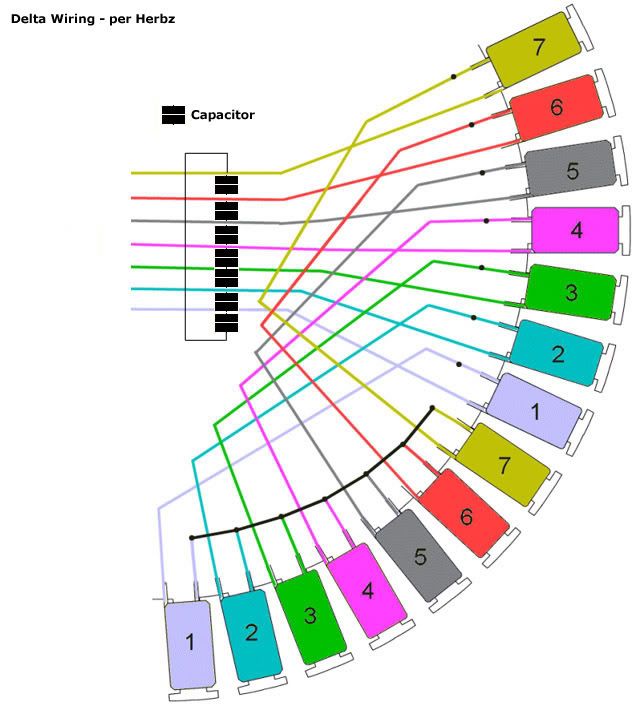
? how would you wire them in star ? Yes the water wheel is VERY relaxing it just churns away and everyone whos seen it loves it.. the old water wheels are far and few between these days.. .5m head.. well funny you should mention that, because early jan i ran a 2" pipe along the bottom of the creek up about 100m and i can get about .5m of head from it at the water wheel.. 2" pipe though makes bugger all difference to the wheel, but ive been toying with the idea of building a turbine of some sort to connect this pipe to.. some design plans would be excellent please.. and i might also have to buy some spoons off you (or eco whichevers easier), as ive been unable to find any here in AUS.. Ill PM you my email.. (Hmm... cant PM on here?!) Thanks again.. Steve |
||||
| herbnz Senior Member Joined: 18/02/2007 Location: New ZealandPosts: 258 |
Hi Steve One more cap phase 1 (grey) back to phase 7 (yellow) That is a delta in Therory works but can in practice with our non sine waves can create a circulating current. Henc reason i mentioned star take 7 caps join one leg each together star point then tap each spare end to one phase. sorry not up to your fancy drawings. Spoons no use for your low head I while hunt out my files on cross flow construction (very similar to fan in car heater) can be made diy. my email add edie1@actrix.co.nz one of the files is scaled in my cad prog do you have facilities DXF files ? I will follow Gills example and place them in my home page and put a link here. Herb |
||||
| Steve9R Regular Member Joined: 24/01/2006 Location: AustraliaPosts: 72 |
ok.. so do you think the star configuration would work better ? does it matter where abouts on each phase i tap the spare leg of each cap ? eg, can they be just before the recifiers ? ( cause that way i can mount them in that electric box at the side of the creek and test different config stators with them too).. Steve |
||||
| herbnz Senior Member Joined: 18/02/2007 Location: New ZealandPosts: 258 |
Hi Steve Having trouble transfering files but have found on net a well document of the design i use (originally mother earth )http://www.cd3wd.com/CD3WD_40/VITA/BANKITUR/EN/BANKITUR.HTM I have a dxf cad layout of the slots . Your 50mm pipe will be no use here @ 100metrs u would only have about a litre / sec maybe 5 watts at 100% Herb |
||||
