
|
|
Forum Index : Other Stuff : LED’s
| Author | Message | ||||
Bryan1 Guru Joined: 22/02/2006 Location: AustraliaPosts: 2155 |
Hiya Guy's, Well this is the best place to continue our dissusion on led's. First if you blokes haven't read Commanda's LED masterclass here is the link. Now circuit 4 is the one I used last weekend and with only 2 resistors,1 transistor and 1 fet what could be easier for making a led light to run off a batterybank. I tested the circuit all the way upto 30 volts and the current never went above 95mA. I've got the led array running off my nife banks so they see 16 volts and dont really start to dim untill the voltage drops to under 11 volts. I've got a few old F&P control boards and they have some fets perfect for the job so this circuit can really be made out of your junk pile. Cheers Bryan P.S. I did ask Commanda if I could use the link and it was approved |
||||
| GWatPE Senior Member Joined: 01/09/2006 Location: AustraliaPosts: 2127 |
Hi all, I have read Amanda's post and her cct component values have to be altered for different voltages. An LED requires basically a constant current source or a constant voltage at the LED operating voltage. A simple constant current cct does not need a FET, only a single npn bipolar transistor and 3 resistors. The current is simply set by a resistor divider accross the transistor base. The trasistor just behaves as a voltage controlled resistor. The higher the voltage, the higher the resistance becomes, keeping the current constant. This means an LED can be operated from a supply that changes voltage. There is proportional dissipation in the transistor with a constant current cct. I am sure ccts are around in texts that clearly show the layout to use. I personally would use a PWM cct to reduce the power loss when the LED is operated from higher voltages. I have used short duration pulses of high voltage [9V] directly across the LED in the past. A PWM buck cct with inductor and diode with feedback regulation could be used from a higher voltage as well. This would be a more complex cct. cheers, Gordon. become more energy aware |
||||
| Bryan1 Guru Joined: 22/02/2006 Location: AustraliaPosts: 2155 |
OK Gordon as you seem be the guru on most things you prove it and show us a led circuit that uses only 4 components apart from the led namely 2 resistors, 1 signal transistor and 1 mosfet, that is superior to commanda's circuit. Bryan |
||||
| GWatPE Senior Member Joined: 01/09/2006 Location: AustraliaPosts: 2127 |
Hi Bryan, I offered a discrete component solution, but a much better 2 component solution is a single resistor with an LM317M device, common as now. This will allow an LED to be run from a 3V-40V supply. The pinout for an LM317M is on page 147 of the 2007 jaycar catalogue. Just connect a 120 ohm resistor between the output pin and the adjust pin. The constant 10mA is obtained between the input and the adjust pin. If you connect the device as I have described, the current will stay 10mA from around 3V all the way up to 40V, with only 2 components. This cct has been around for over 20 years, in many different mags, etc, so I will not take any credit for it. cheers, Gordon. become more energy aware |
||||
| GWatPE Senior Member Joined: 01/09/2006 Location: AustraliaPosts: 2127 |
H Bryan, you asked for a cct. 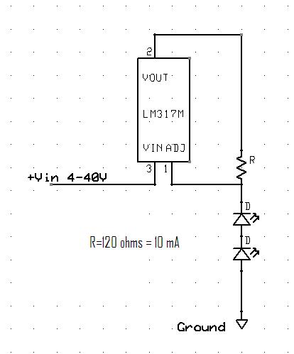
I think this is what you want. The lower the resistance, the higher the current that will flow. For maximum efficiency, series the leds, for the minimum expected voltage. To use at higher voltage than 40V, I wouldn't try. better to use a buck or other type of converter cct. I cannot offer a simpler solution to run LED's off a variable voltage. I think this is the type of cct in those special LED's, that don't need limiting resistors. choose the resistor to give the desired LED current or brightness. The brightness will not change from 40V all the way down to the voltage determined by [# of LED's x LED forward votage] + 1.2V. Of course if the LED is driven too hard, then the intensity will drop over time. cheers, Gordon. become more energy aware |
||||
| commanda Newbie Joined: 12/11/2007 Location: AustraliaPosts: 14 |
This was discussed in the comments attached to part one. <i>The LM317 can be made into a constant current source with just one resistor, but again you have minimum input to output voltage differentials. And none of these have the negative thermal characteristics of circuit 4 that I presented. </i> |
||||
| GWatPE Senior Member Joined: 01/09/2006 Location: AustraliaPosts: 2127 |
Hi Amanda, You have presented some ccts. The LED driving cct you presented, I saw in an Elektor magazine 1983 vol 2/3. I think you will see above,that Bryan did actually request a simpler cct. You have mentioned an LM317, but I did not see any cct relating to an LM317 in any of your comments. Maybe Bryan should be asking you for an explanation about you comment on input/output differentials. Bryan has made a cct. The LED's in his cct example did dim with a voltage drop. I suppose this is useful as an indicator of battery voltage, but there are better ways to do that. What do you mean, minimum input to output voltage differential. The LM317 with a single 120 ohm resistor to set the current, will run a single LED with constant current of 10mA, providing constant light output, on a supply voltage ranging from 4V up to 40V. Do you think the 4 to 40V input range is small. There are circumstances when a negative temp coeff, may be important, but I cannot see it being a critical element here. I will give credit to Ray Marston p9,ETI,circuit techniques, V2, 1982, For his high precision constant current cct that I presented in principle above. Cheers, Gordon. PS. the LM317, I used in testing was scabbed from a dead laptop. These devices also have temperature shutdown as well, [a negative temp coeff]. become more energy aware |
||||
Highlander Senior Member Joined: 03/10/2006 Location: AustraliaPosts: 266 |
I can't find any adjustable regs that can handle 48v. Any ideas ? I'm guessing to run a resistor on the reg input. 
Central Victorian highlands |
||||
andrewf Newbie Joined: 24/12/2007 Location: New ZealandPosts: 15 |
Hi, ive just been trying out some new drivers from national semiconductor. These are certainly not the 'simplest' circuits that you could use, but they work very well, and they are not very expensive, or tricky to put together.. You can even use the online design tools ( my web-bench ) to design your circuit, based on the various paramters you want to use.. In particualar, i've been working on drive circuits to use with 1 and 3W luxeon clones. using a current limiting resistor just is'nt that smart, it generates way too much heat. The driver i've been using is an LM3404HV which is able to run on a input voltage of between 7 and 75VDC. Its a buck psu cirucit, so it requires an external inductor, cap and diode, plus a couple of resistors. Efficency is really good, i've got over 90% out of it in some configurations. Its going to cost you a couple of dollars to build. Its got a logic level dim control, which you can attach a logic level pwm signal to ( such as the pwm output of a pic ), and get dimming control out of. The design is is such that the output current is almost constant across the entire input voltage. Its probably mostly appropriately for higher power circuits, ( say >300mW ), anythign less, you'd probably be best doing something simpler.. for more info, check out http://www.national.com/appinfo/power/led.html I'm using this driver for my christmas led lighting, and i'm pretty impressed by it.. The circuit below is for a single 3W Blue LED, runnign at 700mA, 3.55V, Rd 1ohm. note, i want to dim the led using PWM, so there is no Capacitor across the output. If you just want to run them consistantly, you can reduce the size of the inductor, and put a cap in parrallel.. 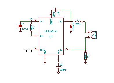
And now also a picture of the first prototype board for this circuit 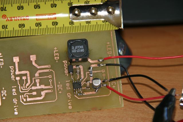 EVERYTHING SHOULD BE AS SIMPLE AS IT CAN, NOT SIMPLER - EINSTEIN |
||||
| woofnumber0 Newbie Joined: 26/04/2008 Location: United KingdomPosts: 10 |
Hi been using mr16x18 sb leds for over a year now,there great have taken surges of over 16volts in high winds before dump load kicks in,there still all working perf.been using 30 of spaced out.at approx 30 ins,in my weekend cabin in the hills.the spread of light is poor,least they dont look as ugly as they 12volt fl strip lights or bulbs, that chuck it when the voltage is to low.least they just dim down.there a lot better than candles.or using my gas lights. |
||||
| independent Newbie Joined: 19/05/2008 Location: Posts: 1 |
This is to Andrewf. If you come across this post. I'm also in NZ and would really like to buy some of those circuit boards off you. I've got a few of those National Semi chips as well and have the perfect project for them. Thanks in advance for your reply |
||||
| The Back Shed's forum code is written, and hosted, in Australia. | © JAQ Software 2026 |
