
|
|
Forum Index : Other Stuff : CNC router finally finished
| Author | Message | ||||
| Gizmo Admin Group Joined: 05/06/2004 Location: AustraliaPosts: 5188 |
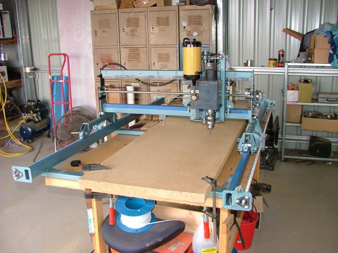
Well it was a hell of a project, took about 6 months of design, redesign, and scrounging for parts. Buts its finally working.
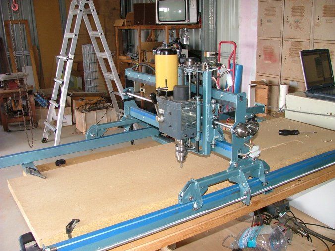
Has a work area of 1200mm * 600mm * 150mm. Below is a closer view of the gantry.
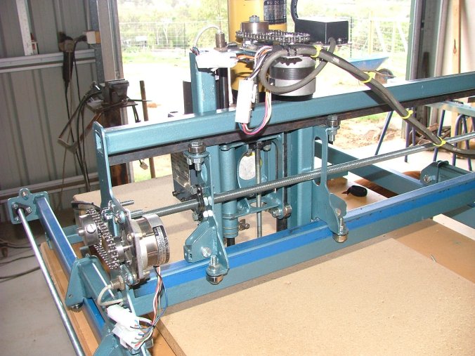
And around the back, you can see the lead screws and stepper drives. Using chain and threaded rod is not the best way of doing this, but they are cheap.
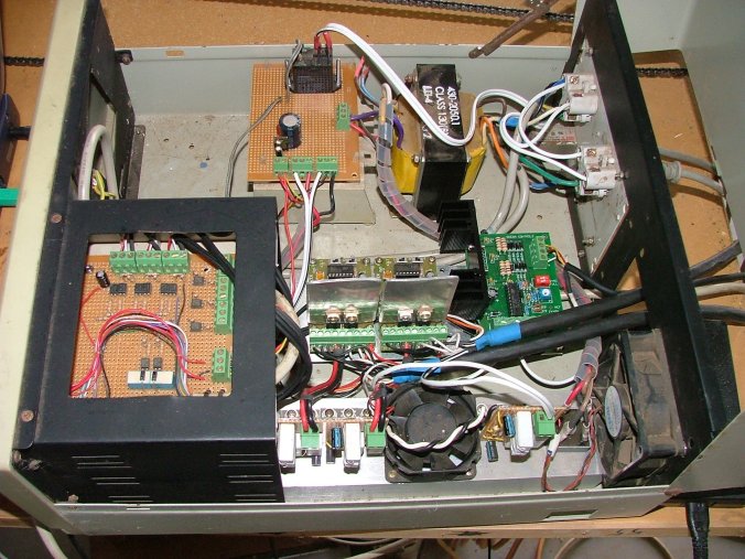
The electronics are housed in a old PC case. I want to upgrade the stepper driver boards, and will need more room so will move to a bigger case in the future. Its not pretty, but it works. The whole thing is driven from a PC using KCam software.
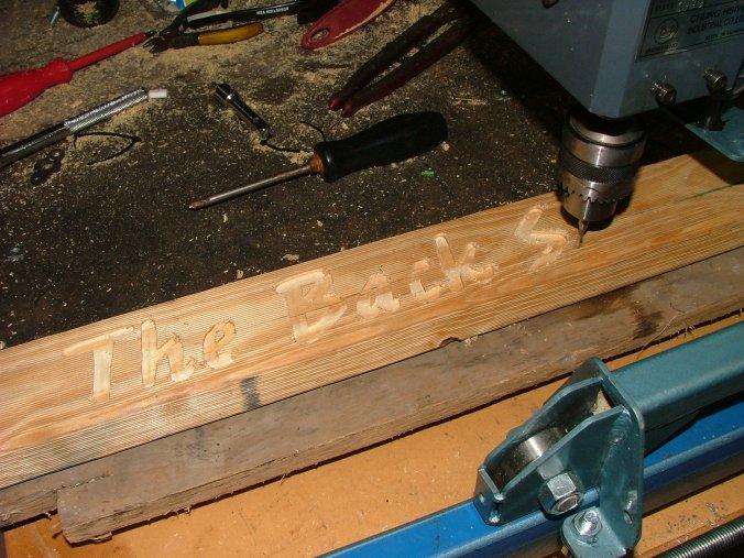
The first serious route job on a bit of scrap timber.
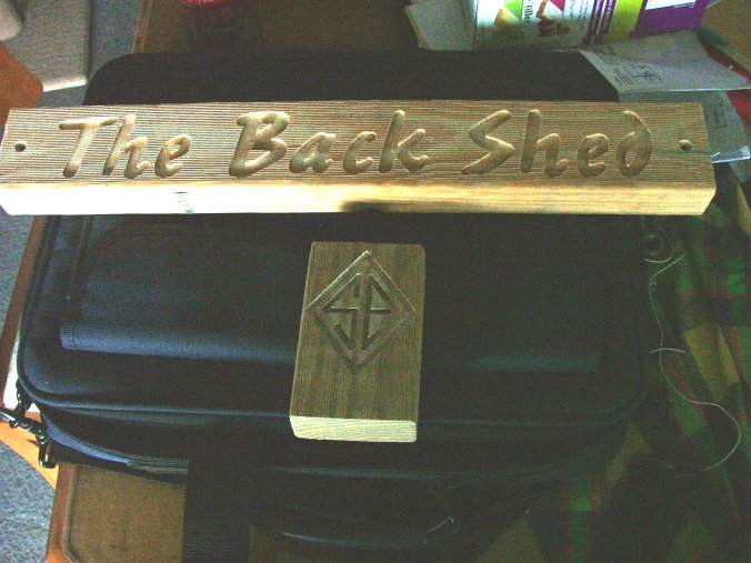
And the results.
The plan is to use the router to make some windmill blades. Well the router is working, but I have a lot to learn before I start making blades. The software uses G-Codes, an industry standard. It will also import DXF files. To rout in 3D the code needs to take off material in steps of about 2mm deep, so a windmill blade would require several dozen passes to get the depths. This is going to be fun. Glenn The best time to plant a tree was twenty years ago, the second best time is right now. JAQ |
||||
Chris Senior Member Joined: 12/09/2005 Location: AustraliaPosts: 146 |
Wow, thats cool... Is that setup using the stepper drive kits from oatley that they make for cnc's? |
||||
| brucedownunder2 Guru Joined: 14/09/2005 Location: AustraliaPosts: 1548 |
Hi Glenn genius, well done - the router head -whats that from? I've got a 5 foot Oregon blade here,finished,it's a spare for my set of 3 . would you like to see if you can copy it ? I think it's a very well carvef blade-lots of drop and twist . Just a thought. well done Bruce Bushboy |
||||
| Gizmo Admin Group Joined: 05/06/2004 Location: AustraliaPosts: 5188 |
Thanks guys. Chris, I started with 3 of the Oatley stepper drives and built my own current regulators. I had problems with the X axis drive ( the one that has the most work to do ) so I ordered a new stepper motor and drive from Ocean Controls ( www.oceancontrols.com.au ). The stepper drive has its own chopper current regulator and can do half steps. The X axis now runs a lot better, the big stepper has lots of power. I will order another motor and drive from Ocean in the near future for the Y axis. I use the half step function on the new drive, runs a lot smoother. If I could afford it I would get some microstep boards. Very smooth, and very expensive at about $300 each. Hey Bruce, Thanks for the offer but I want to build a set of blades from scratch, do all the maths and get it spot on ( or stuff it up ). But you can tell me about the best timber I should use. I've heard Oregon is the one to go for, but its hard to find. Its a mission to even find a bit of pine without a dozen knots in it. Any other suggestions? I did think about glue and clamping timber together to get the size I needed. Glenn The best time to plant a tree was twenty years ago, the second best time is right now. JAQ |
||||
| brucedownunder2 Guru Joined: 14/09/2005 Location: AustraliaPosts: 1548 |
Hi Glenn, so the stepper motor is the router motor-ok. Oregon pine without knots is hard to find , but I can have a look around here for you -there are specialists timber yards around. Spruce is another one (i used it to make small,20 foot, sailing boat masts years ago. Both are a dream to work with. the oregon I have came out of the wool stores in Darling Harbour that burned down years ago , so it's maybe 150 years old , and may have been imported from o/s in those days. Any how, you are doing a fine job , I'll look around here for you .
Bruce Bushboy |
||||
| Gizmo Admin Group Joined: 05/06/2004 Location: AustraliaPosts: 5188 |
Hi Bruce. Nah the router head itself was the milling attachment from my lathe. I never used it, and it often got in the way when using the lathe, so I thought it would be good on the router. It has a electronic speed control and a 2 speed gearbox, plus a 500 watt motor, and its quiet compared to a hand router. The stepper motors drive the router head around the table. Glenn The best time to plant a tree was twenty years ago, the second best time is right now. JAQ |
||||
| Chris Senior Member Joined: 12/09/2005 Location: AustraliaPosts: 146 |
Can your setup be used to cut metal parts to? Or is it just designed for wood? If it could cut metal you could probably sell your windmill kit cheaper with your own cut parts? Or maybe not?
|
||||
| Gizmo Admin Group Joined: 05/06/2004 Location: AustraliaPosts: 5188 |
Hi Chris The router should be able to cut aluminium, but not steel. I used a CNC router a few years ago and when we cut aluminium the router tips had to be spot on, and cut speed very slow. We could speed things up by using coolant, but this was more trouble than it was worth. Cutting steel is best left to plasma, Oxy or Laser cutters. We have all these at my workplace. Our plasma is fast and cheap, but limited to 40mm thick plate. Plus the cut has a nasty kerf angle ( angle of the finished cut, 90 degrees being best )( kerf = cut ). Oxy is slower and more expensive, but can handle steel up to 200mm thick and has a nicer kerf. Laser is has the best kerf, almost perfect and only about 0.5mm wide, and is very fast, but is a very expensive process and limited to 20mm steel. Out laser draws over 65,000 Watts when its running, add to that the cooling systems and CNC, and its about 85,000 watts, or the same power as 85 electric heaters or 40 houses. There is a reason we charge it out at $300 per hour. Plus the laser can also cut most plastics, timber and rubber. It can't cut copper, brass, glass or ceramics. We dont have a waterjet cutter, but they are very slow when cutting steel compared to above. But water cutters can cut just about anything including materials the laser wont cut. I should take some photos and post them on the web site. Glenn The best time to plant a tree was twenty years ago, the second best time is right now. JAQ |
||||
| Chris Senior Member Joined: 12/09/2005 Location: AustraliaPosts: 146 |
Yeah man, take some photos. I always wanted to see how the lazer cutters work. Any chance of a explanation? 65,000w wow thats alot! You would need a fair few 3 phase power points for that sucker right?
Nice work with your CNC mate, very clean. |
||||
| Gizmo Admin Group Joined: 05/06/2004 Location: AustraliaPosts: 5188 |
Hi Chris. I might write up something this weekend. But here's the basics. The laser itself, called the laser "head" or "resonator" is made up of a bunch of tubes about 2 feet long, all connected end to end. Each tube has a electrode at each end. The whole thing is filled with a mix of Co2, helium and nitrogen at low pressure, lower than atmosphere, so its almost a vacuum in there with these trace gases. The high voltage power supplies pass up to 100 milliamps at 20,000 plus volts throught the tubes via the electrodes. This causes the gases to ionise and resonate in the infrared spectrum, producing infrared light out the ends of the tubes. And they glow a real cool purple colour The laser beam is 30mm wide, and has about 5,000 watts of power. This will make metal glow white hot ( and bore a hole through a house brick, very cool to watch ), but it wont cut yet. We use special mirrors to direct the beam to the cutting head, above the steel we want to cut. As the head is moved around the work space, the mirrors move too to keep the beam in the right place. Now the fun bit. We use a special lense to focus this 30mm wide beam to a spot only 0.3mm wide. You can imagine how much power 5,000 watts has when focused to a point. If you use a magnifying glass 6 inches wide to burn paper or wood using the sunlight, you are only focusing about 10 watts of power. Multiply that by 500! This spot will vaporise anything in its path, including steel. We pump ozygen or nitrogen into the cut to blow away the melted and vaporised steel. Move this along the metal surface and your cutting steel. There is a lot more to it, but this give you an idea of how it works. It is an impressive process, there is a lot of computer control to keep it working, and some expensive hardware, industrial lasers usually cost over $500,000 All good fun. Glenn The best time to plant a tree was twenty years ago, the second best time is right now. JAQ |
||||
| brucedownunder2 Guru Joined: 14/09/2005 Location: AustraliaPosts: 1548 |
Hi Glenn, I'm going to visit you sometime this year. Top on the list is a tour of your factory,if you invite me. Concreting under the house at present ,hope to finish (They) next week -wow, a new BIG workshop , hehehe.
Good explanation of the laser- can't wait to see it Bruce Bushboy |
||||
| Chris Senior Member Joined: 12/09/2005 Location: AustraliaPosts: 146 |
Wow thats amazing glenn... Sounds really cool. Do you need special goggles to view the beam? How is it the lazer can cut thru steel but doesnt cut thru the mirrors or the base of the workbench...? |
||||
| Gizmo Admin Group Joined: 05/06/2004 Location: AustraliaPosts: 5188 |
Hi Chris The mirrors are make of a special material that reflects infrared light. And they are cooled with the cold water from the chiller. The optic path is also fed filtered air to keep the dirt out. The laser bed is made up of ribs of steel, and these are sacrificed. A bed is slowly eaten away and replaced every couple of weeks. Remember how I said the bean is focused with a lense? This lense has a focal distance of 7.5 inches, so the lense is about 7.5 inches above the cut sheet. Most of the beam energy is abbsorbed in the cutting process, but the rest goes out of focus as it moves down under the sheet. By the time it gets to the trays ( trays collect the molten steel and scrap ), the beam is about 10cm wide and lost a lot of its energy. Its still hot, but wont melt anything. Plastic safety glases are all they the operators need to wear, and only in case there is a scattered beam or spattered metal. The laser tip sits about 1mm above the cut sheet, so there is no chane of getting a finger in there. Its actually a fairly safe process. Glenn The best time to plant a tree was twenty years ago, the second best time is right now. JAQ |
||||
| Chris Senior Member Joined: 12/09/2005 Location: AustraliaPosts: 146 |
Sounds really cool. That thing would put your powerbill up pretty high ey? Whats your company's name? |
||||
| Chris Senior Member Joined: 12/09/2005 Location: AustraliaPosts: 146 |
Today at my tafe, we had a walk thru the mechanical engineering part of my tafe. They have this machine that cuts metal with wire. The wire is no thicker then fishing wire but its obviously metal and it can cut thru huge thicknesses of metal. Whats cool is what it cuts on one side can be different on the other because it can flex the wire. Apparently it works by sending a voltage thru the wire. I dont quite understand but its supposed to be extremely accurate. I just thought you guys might be interested  |
||||
WXYZ Newbie Joined: 30/04/2006 Location: CanadaPosts: 20 |
Gizmo, Joseph here. Here is a picture of my cnc machine I built last year. 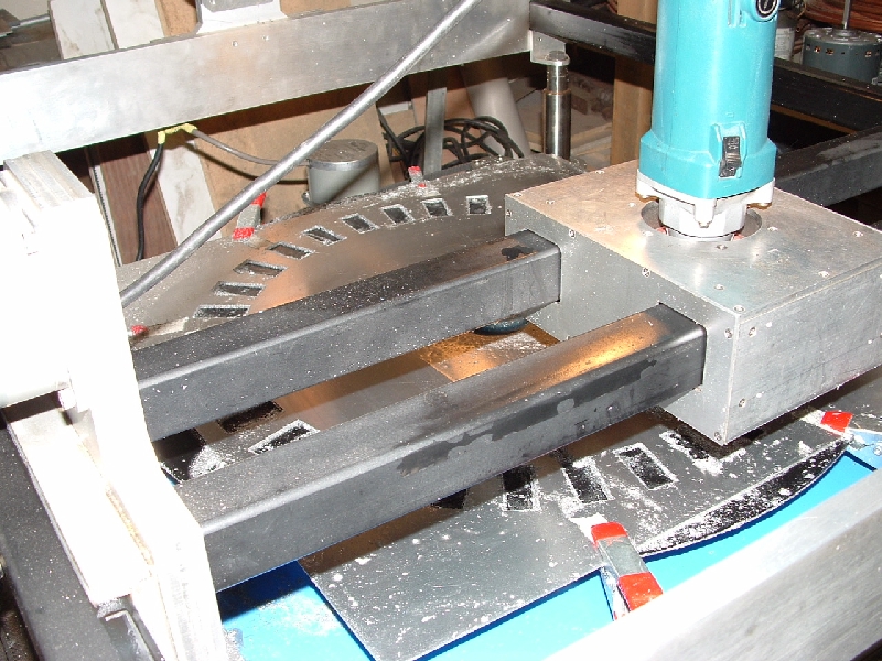 I am cutting 6063 aluminium. A template for a magnet rotor, first cuts on my rotary table W bed. I am cutting 6063 aluminium. A template for a magnet rotor, first cuts on my rotary table W bed. "Failure is an option." |
||||
| tray Newbie Joined: 27/08/2006 Location: New ZealandPosts: 4 |
Hello, I'm looking into building my own CNC router. Taking advantage of other peoples learning experiences. Glenn I'm a little eunsure of your preferred stepper motor control scheme. Did you settle on the oceancontrols controller/interface? If so what interface do you use? I was looking to us the serial port version, oceancontrols stepper driver and KCAM. Is this all the requirements for brains? Thanks, Trevor |
||||
| Gizmo Admin Group Joined: 05/06/2004 Location: AustraliaPosts: 5188 |
Hey Trevor I ended up using the Ocean Controls stepper driver, the one with half steps and current control, KT-5191. And for steppers I used their 23HD803 motors. I drove the stepper drivers direcly from the parallel port. Other than that all you really need to get up and going is a good power supply, at least 25 volts at 3 or more amps. I've read good articles about the serial interface board, but havn't used it. Not sure if KCam supports it, as the KCam author had a family death a year ago and is no longer supporting the software. Bummer, its a good program. One of the biggest problems with using a parallel port is the PC spends most of it time sending out the signals for each step, but that serial interface means the PC just needs to send the basic info out, and can continue working on the next set of commands. The KCam site also has something called the "Max Stepper", which will work with KCam. If Max Stepper works the same was as the Ocean controls serial interface thingy, then it should work. Glenn The best time to plant a tree was twenty years ago, the second best time is right now. JAQ |
||||
| tray Newbie Joined: 27/08/2006 Location: New ZealandPosts: 4 |
Thanks Glenn, Your referencing the parts (by part number) has clearly described your system. I think I will look further into the Linux EMC project to see what can be used there instead of KCAM. As you say it's a shame because the software (KCAM) listed some nice features. Comments regarding the serial port also agree with my understanding, parallel port comms. really are bit of a hack. Still I suppose people have got machines going with it. Again, thank you. I will carry on looking into this subject. Regards. |
||||
| The Back Shed's forum code is written, and hosted, in Australia. | © JAQ Software 2026 |


 . Our laser is a "folded" laser consisting of 12 tubes, 2 rows of 6 with mirrors to make it a straight line as far as the light is concerned. The gas gets very hot very quick, so it has 2 big turbines that circulate the gas through cooling units. The gas is circulated at 0.9 mack, or just under the speed of sound! The turbines are about the size of a microwave oven, take 2 minutes to get up to running speed, and cost $70,000 each! The cooling units are fed chilled water supplied by a refrigeration unit, about the size of a phone booth.