Notice. New forum software under development. It's going to miss a few functions and look a bit ugly for a while, but I'm working on it full time now as the old forum was too unstable. Couple days, all good. If you notice any issues, please contact me.
Gill Senior Member Joined: 11/11/2006 Location: AustraliaPosts: 669
Posted: 03:49am 12 Apr 2008
Copy link to clipboard
Print this post
Good thinking there Gordon. That is certainly the case.
A Hydro has a fixed head, so a fixed pressure. This would be like a wind generator that has an exact [say] 30kmph wind blowing from the exact same direction 24 hours of the day. Wind and solar just don't come anywhere close to these babies and the setup costs are a fraction of the other units with the same peak output. I estimate that on an overall comparison my 30Amp hydro is 15 times better than my 30Amp solar. But I digress.
There are two aspects that require control on a hydro. The first is as Gordon has identified and proposed, a non electrical(power dumping) solution to over charging of the battery.
The second is drop in available flow.
By explaining the situation with flow I'll then explain how I'd modify Gordon's proposal to cover them both.
When flow rates drop, the jet size still allows the max current to flow but the supply to the inlet drops. As a result it sucks in air. This may well self purge under normal max flows but with more air the pressure drops causing flow to become erratic with loud cracks and bursts of air severely stressing the runner and attached generator. This condition can be avoided by fitting a jet size that matches or is less than the input flow.
Like reducing the flow when the battery is full so to a reduced flow can be achieved by reducing the jet size.
If the jet size can be controlled, this can be initiated by either a full battery or reduced flow at the intake.
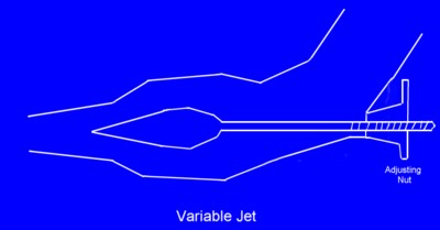
There are two methods of reducing jet size. The first is as Gordon has suggested ie. multiple jets. the second is an adjustable jet. The industry standard is something like this sketch:
In both cases a method of turning a valve is needed, battery voltage and header dam(intake)levels need monitoring and the data sent to the controller circuit(several hundred meters at least). The circuit then controls the valve turning device.
Whilst it is possible to reduce the flow and it's resultant power out, efficiency drops off and for the reduced flow problem an accompanying winding out of the generator rotor is needed to achieve max efficiency for this new reduced flow. I have no solution to achieving the highest efficiency (a lower but max output) for this reduced flow.
Any takers??
was working fine... til the smoke got out.
Cheers Gill _Cairns, FNQ
GWatPE Senior Member Joined: 01/09/2006 Location: AustraliaPosts: 2127
Posted: 05:44am 12 Apr 2008
Copy link to clipboard
Print this post
Hi Gill,
what you have drawn, is a typical metering valve, similar in principle to that used on model glo/diesel engines.
This arrangement does not effectively very the jet size, but just restricts the flow through it. This will result in poor efficiency of the jet and low resultant hydro dynamic efficiency.
I do remember performing tests [the impact of a jet] at Uni. I cannot remember all the specifics, as this was 30 years ago. Perhaps a reader with more recent knowledge can help out.
Perhaps a more useful solution to the flow drying up might be to incorporate a header tank. The same control cct for battery control could incorporate a level sensing element in the header tank. This would also regulate the flow and prevent the entrained air problems. At less than 10% then the user may need to make an adjustment.
I do not see a need for a continuously variable jet. The average power will still be determined by the movement of the total average mass of water.
The rpm is determined by the velocity of the water jet, impacting on the turbine cup/blade. Consider a turbine with 2 jets, one providing 10% maximum power and the other 100%. A sweet spot should be obtained at the upper and lower operating points. The maximum efficiency of the turbine is maintained. The turbine should load more as soon as the battery voltage drops. The power will be fully controlled by the available water and self regulating. The power is related to the mass flow of water at that jet velocity. The system would oscillate between 10% and 100% max power, but this would not be a problem with a battery system. This could extend the time a system operates without user intervention.
Is it possible for a micro hydro operator to see if a system can operate at say 10% water flow with a separate jet without adjusting the rotor... Gordon.
become more energy aware
Tinker Guru Joined: 07/11/2007 Location: AustraliaPosts: 1904
Posted: 10:17am 12 Apr 2008
Copy link to clipboard
Print this post
OK, here's another idea. It may sound silly on a small scale hydro but I believe its done on large scale systems.
a. run the thing at full capacity.
b. use the excess power to pump water back up to wherever it originates (header dam?)
TinkerKlaus
Gill Senior Member Joined: 11/11/2006 Location: AustraliaPosts: 669
Posted: 10:53am 12 Apr 2008
Copy link to clipboard
Print this post
Tinker,
Great idea for excess wind generating capacity, but a waste of energy for a hydro system. With inefficiency and all other losses it would take more power to pump the water back up hill than it generated from it's way down. Better to store the water uphill in a huge holding dam waiting for battery drop and the required recharge.
Because wind can't be stored as such converting excess to hydrogen for storage or by pumping water up-hill and storing it for later generation is an excellent idea. Thank you. was working fine... til the smoke got out.
Cheers Gill _Cairns, FNQ
Gill Senior Member Joined: 11/11/2006 Location: AustraliaPosts: 669
Posted: 01:03pm 12 Apr 2008
Copy link to clipboard
Print this post
Gordon,
I think I need to differ from your approach in that your system is designed on the premise,
"Would it not be better with a battery system to just reduce the water flow to a level that maintains the generator RPM at a level that maintains battery voltage.", and that can be met by switching to an additional fixed jet of say 10%.
I agree with your query yet I disagree with your method of achieving it. If the battery had no other losses to it's fully charged state than leakage then theoretically a small fixed jet could compensate for this loss. However an RE system is a dynamic beast with varying loads as well as the fixed leakage. A fixed jet will not maintain a stable float voltage without frequent top-ups with the main jet. Why have a small fixed jet at all? Simply turn the main jet on an off in the same manner we do with Bang-Bang shunt regulators. Much simpler as I would have issues with a 10% jet with no accompanying reduction in generator load per RPM as mentioned earlier.
Of special concern with ANY design is that any transition between flow rates be done very slowly to avoid hammering in the line. This causes pipe movement and possibly busting a coupling. Relief devices may be available but best to avoid the problem in the first place.
This is not correct as I understand it. I feel you may not fully grasp the reduction in gen load (by winding out the rotor)to bring the rpm back up to max(gives max amps for that jet size). This may not be such an issue with battery regulation as we have too much power any way, but with reduced water flows it is most important to still get the mostest power out.
For my system maximum amps are obtained at 1012 to 1015 rpm. If the jet is reduced, the gen rotor must be backed off to reduce gen loading and bring the rpm up to the stated level. I suspect that gen testing in a lathe does not identify this issue as the lathe power copes with all settings but a hydro has very fixed power IN, as set by the jet size. This becomes very clear on a hydro yet I find it often difficult to translate this to the opperation of my wind gen. I think this is the resoning of herb NZ's suggestion to Bruce to fit a power in(torque) metering device.
I see a PWM control of a variable jet as the way to go with initial regulation from a header tank water level sensor then further reduction as required from a monitor of battery voltage. Still this can not give max effiency as required with the reduced flow and would be more trouble than the avoidance of manual adjustment is worth.Edited by Gill 2008-04-13was working fine... til the smoke got out.
Cheers Gill _Cairns, FNQ
GWatPE Senior Member Joined: 01/09/2006 Location: AustraliaPosts: 2127
Posted: 01:01am 13 Apr 2008
Copy link to clipboard
Print this post
Hi Gill,
When you say you reduce the jet size, are you just adjusting the water flow with a valve in the water input line?
Gordon.
become more energy aware
herbnz Senior Member Joined: 18/02/2007 Location: New ZealandPosts: 258
Posted: 01:48am 13 Apr 2008
Copy link to clipboard
Print this post
Hi
subject is become very complex for what is well sorted out in the Hydro scene. Use the KISS principle.
If control of water flow is necessary very expensive motorised valves are required soliniods tempting but create water hammer surge chambers can be used.
I do have one of my units fitted with a honeywell valve that i picked up for nicks, this is operated when water flow is low rather than change the jet i shut down untill pressure builds up maintains operation at optomin , but breaks the kiss principle.
My whole system 3 Hydro's ! windmill 4 solar panels has evolved over the 15 years . The main control is usually via a smart relay to my 230 standart water heater not PWM I give 10 sec bursts if above 29.6 v although if this is hapenning regulaly it drops to 26 v float.
At present I am trialing a commercial PWM Tri star to a DC load. However to get my 230 volt dump I have a timmer set at 10 sec on the DC Dump so in effect the no Dc flows. Reason for trialing this is the very atractive price of the units now days $190 got all protection logging etc built in.
I personally do not like or see the necessity of PWM but these commercial units disagree here. Although the Tri Star unit I have trialed here has an option o on/off .
One unit that I have sold I controlled via a smart relay and 230 volt water heater however as it was capable of over 1000w I fitted an emegancy dump if other failed by shorting out the AC stator. This because it was operating in current limit did give overspeed but shut down the output overspeed no problem .
Above a few ramblings
Herb
Gill Senior Member Joined: 11/11/2006 Location: AustraliaPosts: 669
Posted: 04:59am 13 Apr 2008
Copy link to clipboard
Print this post
Gordon,
Theoretically, yes; practically,no.
Theoretically:
A valve in the water input line is equal to a resistor(ohms) in an electrical circuit. The Head is the pressure so is equal to EMF(Volts) and the flow in litres per sec is equal to current(Amps). A jet is also a resistor to the flow.
Practically:
A jet serves to concentrate the water(and the power in it onto the runner's cups. A valve at the intake end of the pipe(or anywhere in the pipe) with equal resistance and no jet would not produce a workable result though the theory figures of pressure, flow and resistance would calculate otherwise. It's a bit like a stove heating element and an light bulb, both are resistors but each has a different physical effect. It is the physical effect of the jet bought on by it's resistance that is essential for power transfer to the runner and subsequent gen drive shaft.
Water Power:
I guess by using ohms law the power in the water downstream of the jet could be calculated. Firstly the head pressure must always be maintained and so be the same but the flow and jet can alter. If the available flow is say half then the jet area must then be halved to maintain the head. As a simple man, I use ohms law to then say the water power delivered to the runner is halved. Though it may well not be proportional but follow the dymanics of wind where power is volocity*area^3??
Power In, Power Out:
If I maintain the same head and reduce the jet size, the generator output will drop. If I then wind out the rotor, the generator output will rise significantly. It will of course never rise to to near the original output.
Let me give some ball park figures for those number-crunchers.
IN_initial:-
Head = 58 meters, Flow = 2 litres sec??, Jet = 95mm^.
Out_initial:-
Volts = 14v, Amps = 32Amps
I hope my rather practical approach has sufficient info to relate the normal hydro setup and the physics they satisfy. Unfortunately I've just this week run out of water so my wet season is over for the year. Hope the wind picks up.......Edited by Gill 2008-04-14was working fine... til the smoke got out.
Cheers Gill _Cairns, FNQ
GWatPE Senior Member Joined: 01/09/2006 Location: AustraliaPosts: 2127
Posted: 07:28am 13 Apr 2008
Copy link to clipboard
Print this post
Hi Gill,
There are two issues here, battery regulation and throttling with reduced flows.
Given your lengthy description, and the issues with changing water flows.
At maximum flow you have 2L/s. A 200L drum gives 1.5 minutes operation. Have a level sensor in the drum. As long as the turbine can start with the full flow and water head from a stop, then
I would incorporate an electronically controlled ball valve in the water line to the jet. This valve is controlled by the water level in the drum using 2 sensors giving hysterisis and battery voltage with an upper and lower setting. There would be only 1 jet. The optimum efficiency of the turbine will be set once with this jet. The unit will cycle with the battery voltage and available water. The unit will conserve the water supply.
There will be a slight loss of total output as the turbine will have a runup delay. There will be a slight transmission loss as the unit will be always operating at full power. A single picaxe 08M could easily control this unit.
As the water supply dries up, you may adjust the rotor once. This will be from maximum power during good water availability to the maximum efficiency as the flows drop.
The ON/OFF control is probably going to extend the mechanical life as entrained air problems will be eliminated. A minimum 90 second ON or OFF cycle time should be tollerable as it will only occur with the low flow period. The battery regulation will cycle on the battery load and timing within the micro.
Will the turbine start in the manner I proposed? I would not use a solenoid! How long would the turbine take to runup to full output from a stop? ... Gordon.become more energy aware
Gill Senior Member Joined: 11/11/2006 Location: AustraliaPosts: 669
Posted: 12:04pm 13 Apr 2008
Copy link to clipboard
Print this post
Gordon,
This latest method seems to cover both Hydro variables satisfactorily and with no loss of efficiency. I see the larger the holding capacity at the top the longer the cycle period. This would be an advantage for those with the geography to exploit it.
The system you propose will not have any problems with starting-up, though the valve is best located at the discharge end, but I don't see any problems with doing that.
The only concern is as you have queried, being turn ON and OFF times. I take about 10 - 15 secs to turn ON and about 15 - 20 secs to turn OFF. I keep an eye on the pressure gauge to ensure it doesn't swing to much.
As you say, fairly light on the electronics too with the PICAXE 08M suiting perfectly.
Now all I need is the RAIN. was working fine... til the smoke got out.
Cheers Gill _Cairns, FNQ
GWatPE Senior Member Joined: 01/09/2006 Location: AustraliaPosts: 2127
Posted: 12:12pm 20 Apr 2008
Copy link to clipboard
Print this post
Hi Herb,
I am intrigued. What is a smart relay? Is it what I would call a hockey puk-SSR[Solid State Relay]? [usually black in colour and about 60mm x 35mm x 20mm]. .. Gordon.become more energy aware
herbnz Senior Member Joined: 18/02/2007 Location: New ZealandPosts: 258
Posted: 11:44pm 20 Apr 2008
Copy link to clipboard
Print this post
Hi Gordon
No not above they are the commercial development of the micro computer (pic etc ) Basic units have 12 inputs 4 analogus, 4 outputs a 6 line screen . input buttons, etcinbuilt power supply protection , programming about 100 instruction set , ladder logic , function block, or flow logic programming languages from PC or you can ser up with fitted push buttons and screen.
I have mentioned before and shown pic cannot remeber topic but not any interest so shut up.
Many brands on market getting cheaper by the day doubt if you could built any pic axe project for the price these especially if you added labour development time.
Herb
GWatPE Senior Member Joined: 01/09/2006 Location: AustraliaPosts: 2127
Posted: 12:26am 21 Apr 2008
Copy link to clipboard
Print this post
Hi Herb,
I know what you mean. I have a Mitsubishi alpha, badged by HPM. 6 analogue 0-10V inputs with 4 relay outputs and 4 line display, with softkey buttons. I had tried one of these units to control my system. Not much success. I have gone back to a BS2 with 20x2 LCD and 2 x PicAxe 08M. My gridfeed wind, solar and offpeak charging all work together well with the parallel processing of 3 micros. I may have to tweak the temperature compensation for the battery still. The alpha was good as a display module. I did eventually run out of memory on the basic unit. I will be using it to monitor my 2 windmills. It will display input volts and amps and calculated power for each mill and on a second display page battery volts and generated battery amps. Logging is not a strong point. I probably won't even use any outputs. The one I have is 24VDC supply. There are mains powered units as well. .. .. Gordon.become more energy aware
herbnz Senior Member Joined: 18/02/2007 Location: New ZealandPosts: 258
Posted: 07:43pm 21 Apr 2008
Copy link to clipboard
Print this post
Hi Gordon
I am not aware of you model i assume it is an early model I use Zelio brand . I would like to say for the benifit of others that are watching that thes relays are very powerful and the easy answer to those that dont have the times and skills that Gordon has. As they are setup to be capable of servicing many different parts of the industry they may lack super fast processing speed but are more than satisfactory for all our aplications, In fact using function programming language they have instructions that use event interupt features that allow high dpeed processing. The main thing I have found frustrating is when i wish to log data ones i have found no means of storing the data and i need to leave the computer connected on monitoring and store on files there.
I've only just read a few coments in here regarding speed of water flow to create a mini hydro. I'll add to your idea. If the water suply was slowed down to flow through an S bend like a toilet, the weight of the head of water After the S bend would always drop/flow at the same speed. A toilet float value could be used to controll the head of water before the S bend. sh*t Idea ?--Anthony
Petrol FWD & Electric RWD
Warpspeed Guru Joined: 09/08/2007 Location: AustraliaPosts: 4406
Gill Senior Member Joined: 11/11/2006 Location: AustraliaPosts: 669
Posted: 03:39am 11 May 2008
Copy link to clipboard
Print this post
Thanks Tony,
I see the 'wicket gate' performs the same function for the Francis turbine as the variable jet does for Pelton turbine. Being correcting/directing the flow to the runner and providing adjustment for varying flow rates.
Quite efficient, but much to complex engineering for my DIY F&P setup but perhaps someone else sees some potential. It certainly has the hydro control problems sorted. was working fine... til the smoke got out.
Cheers Gill _Cairns, FNQ
Warpspeed Guru Joined: 09/08/2007 Location: AustraliaPosts: 4406
Posted: 05:28am 11 May 2008
Copy link to clipboard
Print this post
I just pulled one of these apart myself just a few minutes ago to measure it up. Inlet and outlet both 42mm to give an indication of size. And the curvature profile of the turbine blades look exactly like the pictures of the big full sized hydro Francis turbines.
Both rotor and movable vane assembly are always made from stainless steel, housing is fairly solid cast iron.
Most modern turbodiesel turbocargers use these variable vane turbines. This one is from a six cylinder Nissan Patrol. For anyone feeling a bit adventurous this would probably make a very efficient mini hydro. The vanes move freely from fully closed against each other, with almost zero leakage, to almost the fully radial position. The movable vanes all operate together from a single operating lever.
Vanes are designed to have balanced hydrodynamic pressure, so there is minimal force required on the vane actuating lever.
Maybe not for everyone, but at least as far as I know an original Warpspeed idea.
Cheers, ĀTony.
Warpspeed Guru Joined: 09/08/2007 Location: AustraliaPosts: 4406
Posted: 05:45am 11 May 2008
Copy link to clipboard
Print this post
In a turbo, these turbines typically have around 75% efficiency gas driven at very high rpm. Water driven at much lower rpm it should potentially be even better than that. With both the vane mechanism and bearings packed with waterproof marine grease I believe it should work pretty well.
Just remove the compressor housing and centrifugal compressor wheel completely, and replace it with a pulley or a shaft coupling. Dead easy to do.Cheers, ĀTony.
Gill Senior Member Joined: 11/11/2006 Location: AustraliaPosts: 669
Posted: 06:07am 11 May 2008
Copy link to clipboard
Print this post
Yes! Yes! Yes! What a great idea. The thought of creating that impeller and then the wicker gate is just too daunting a task for me, but to convert an existing unit, now that has potential. Maybe the 42 mm inlet is a little large? To go from air to water I think there'd be a need for less volume and more pressure. I wonder if the wicker gate alone would meet that need? My supply line is 50mm poly to a jet size of 11mm for the pelton. Just trying to evaluate what it's supply needs would be.
Any one with a degree in hydrodynamics?
I think there is only one way to know for sure. Get one and try it. You don't really need that Nissan Patrol do you? The wife could drive you around in Mum's Taxi, yeh?
Let's see what other suggestions / considerations are around. Maybe there's some pitfalls to avoid too?
was working fine... til the smoke got out.
Cheers Gill _Cairns, FNQ
Page 1 of 2
Print this page
The Back Shed's forum code is written, and hosted, in Australia.