
|
|
Forum Index : EV's : Ma-Sea Solar boat
| Page 1 of 3 |
|||||
| Author | Message | ||||
Trev Guru Joined: 15/07/2006 Location: AustraliaPosts: 676 |
Further development of the solar boat concept. First experiments http://www.thebackshed.com/forum/forum_posts.asp?TID=8230&PN=1 I bought some poly pipe 300mm diameter some time ago. 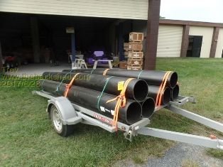 The first was to see if the pipe could be straightened. We left it with curve up in the sun for many days. Every day the pipe would just bend up further. The heated side expands, making the pipe curve more. So turned one pipe over exposing the concave side to the sun and it straightened and then bent the other way. Let it cool in the shade and it just went back to original curve. So thought to make a fibreglass panel and shove it through the pipe, but still no success to straighten the pipe. So..... too bad, we will use the pipes with the curve in it. This is another Dad and son (& son) project. We set about making a cone shape plug from polyurethane foam. Cut rough pieces and glued them together, then sanded out the shape. Sprayed with flowcoat and sanded that off to a reasonable smooth surface. Then take a mould off this shape and make 4 cones from the mould - 2 for the front and 2 for the back. Glued one cone in the first pipe. 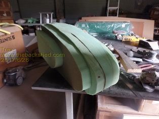 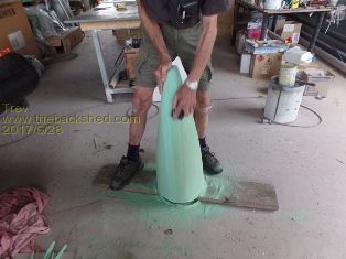 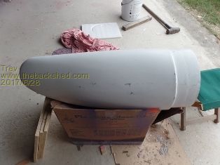 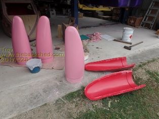 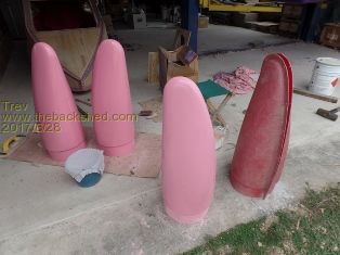 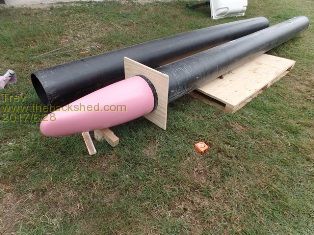 Trev @ drivebynature.com |
||||
| Boppa Guru Joined: 08/11/2016 Location: AustraliaPosts: 816 |
I didnt have a solar boat, but for several months I did have an electric one I had a 24v 87lb electric trolling motor, and I was actually surprised by its performance, it could push the 14fter along about the same speed as the 6hp did When the petrol motor chewed its g/box out due to netting, I used the trolling motor for a few months until fixing the petty motor and was surprised that 2 4wd hilux batterys was capable of several hours of fishing down Alligator Creek, the first few times I chucked my homemade petrol battery charger in just in case (lawn mower motor hooked up to 12v 100a car alternator) but never actually needed it That motor pulled about 40A at 24v, I often thought that a full length `solar canopy' would be able to put that out easily on a 14fter, plus some batts for backup could easily be carried by my boat (its official payload is 4 people @120kg each according to the old sticker it had) |
||||
| Trev Guru Joined: 15/07/2006 Location: AustraliaPosts: 676 |
With nose cone glued in, we then stood the first pipe up on the shed roof and filled with foam - a 2 part polyurethane foam mixed as liquid and poured in. The pieces of ply were there to help in holding the pipe round. After the first one then onto the next. 6 pipes to fill. Extra foam was cut back to where it needed to be, some with internal locator, so cut back inside the pipe. 2 pipes were started with internal locator as a plug to stop the foam falling out the bottom and 4 pipes started with the cone on the bottom. For external locators we cut a short piece off the end of the pipe, reduced the diameter and welded into the end as a locator. We did this before we started making the nose cones. The locator is to join 3 pipe lengths together. 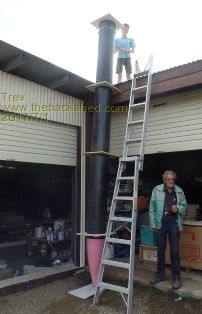 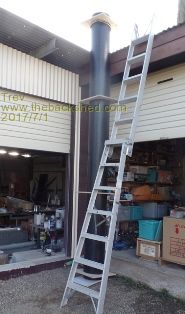 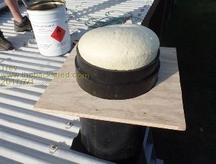 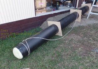 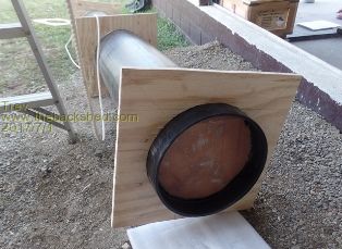 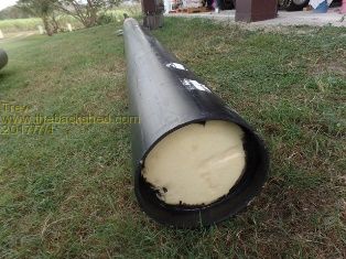 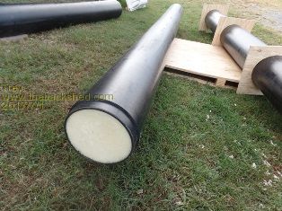 Trev @ drivebynature.com |
||||
| Trev Guru Joined: 15/07/2006 Location: AustraliaPosts: 676 |
Started the side panels. Cut 50mm structural foam, routered corners, drilled holes and filled to add strength where bolts will go through. Joined up the foam with 50mm fibreglass between joints to add strength. Glassed over the first side. 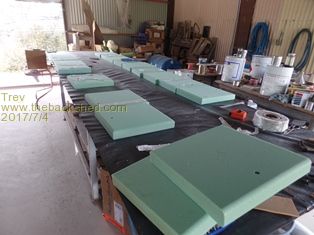 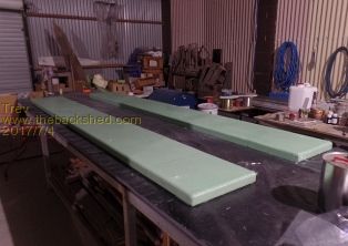 Trev @ drivebynature.com |
||||
Amelia_Williams Newbie Joined: 06/07/2017 Location: PhilippinesPosts: 1 |
This is awesome and good luck to ya! Have a speedboat in the garage shed but interested on the outcome of this one. Keep us updated. Create the things you wish existed! |
||||
| Trev Guru Joined: 15/07/2006 Location: AustraliaPosts: 676 |
With fibreglass on only one side, we put them aside and started the deck. More cutting and joining up with the 50mm fibreglass tape as ribs to strengthen the structure. All the long ways cut and joined and then cross ways cut and joined. A grid of stiffening ribs. 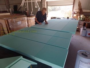 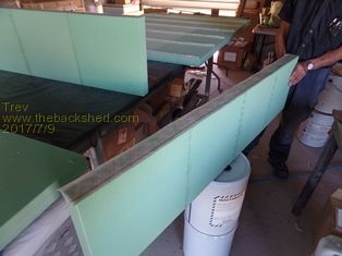 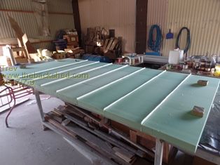 Got the motor out for a closer look and measure up to work out the engine mounting pod. The height of the motor mounting had to be lower than where I wanted the deck to be. We used 12mm structural foam to create the shape and glassed over on one side. When the resin was set, then turned over and glassed on the other side. With a strong stiff construction then was to thicken up the part where the motor will be clamped on. Here is a picture of the motor that we will try first. It is rated at 10kW, or said to be equivalent to a petrol 20HP. 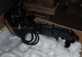 Attention was also turned to setting up to make a mould for pieces to hold the pipes on. With the deck joins all set we then glued on the sides and braced square until glue set. 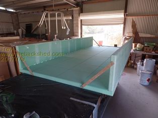 Then fibreglassed over and fibreglassed the motor mounting pod on as well. 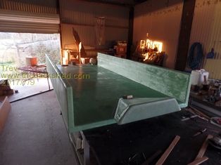 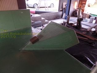 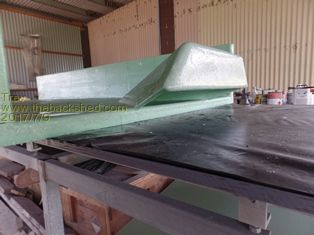 Back to the pipe join mould, gelcoated, fibreglassed, and braced. 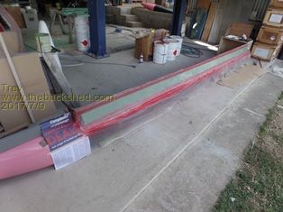 Trev @ drivebynature.com |
||||
| Trev Guru Joined: 15/07/2006 Location: AustraliaPosts: 676 |
Next was to flowcoat the underside. 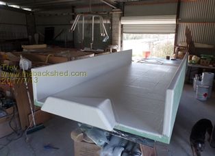 Took the pipe join mould off the pipe. It was very rough because the sticky tape formed wrinkles as the pipe moved from day time heat to cool night temperature. I had already sprayed the gelcoat so nothing I could do about it then. We patched it up a bit and just use it. First flange on the mould. 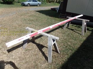 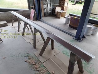 Turned the body over and had to check out how the electric outboard motor would sit - see if we had our measurement right. Should be pretty good. Have to thicken up the mounting board as the motor clamps don't wind in that far. 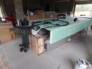 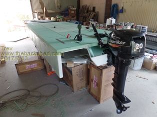 2 pipe join flanges off the mould and third gelcoated. We did glass the 3rd one up late today but no picture. 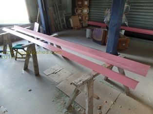 A little more work done on the top of the body. 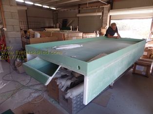 Trev @ drivebynature.com |
||||
| Trev Guru Joined: 15/07/2006 Location: AustraliaPosts: 676 |
The basic body of the test boat is now finished. 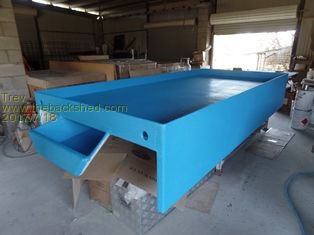 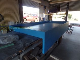 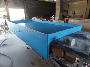 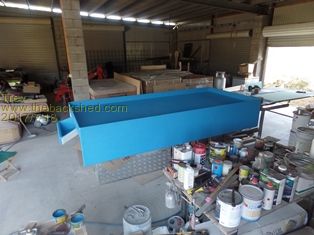 Trev @ drivebynature.com |
||||
| Trev Guru Joined: 15/07/2006 Location: AustraliaPosts: 676 |
Fitting the pipes was a bit of a challenge. They must stay parallel. 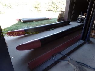 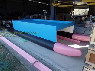 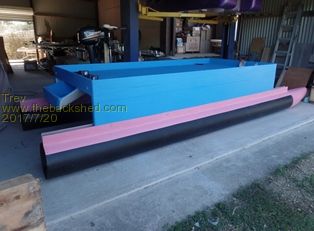 Lifted onto the trailer. Fit the motor and batteries. And test it, see if it runs, and yes it does. I had the controller programmed at the factory to run forward controls, but one steering bracket got missed from the box, so temporary, I will use the joystick as forward and reverse and the makeshift alloy flat bar as steering handle. I can't use the normal tiller steer on the motor as the back of the boat is in the way. 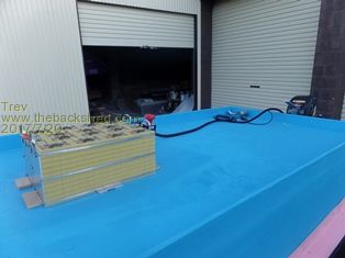 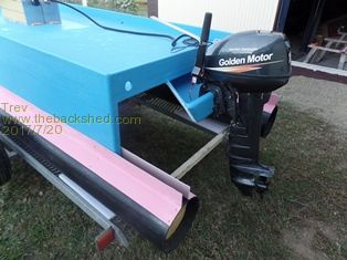 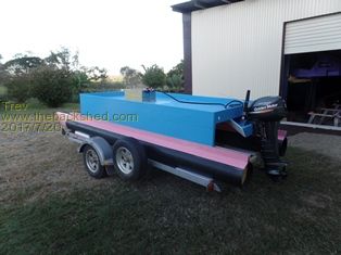 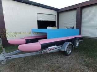 Trev @ drivebynature.com |
||||
| Trev Guru Joined: 15/07/2006 Location: AustraliaPosts: 676 |
Got it registered. Painted the rego label. Part of the registration, they wanted a name to be on the boat, so while I call the design, Ma-sea, mother of the sea. (a twist of Marcy, my wife), we came up with E LAD. This is the small version of the big one, so it is the LAD, but the Electric LAD. (a twist of Dale, my son) 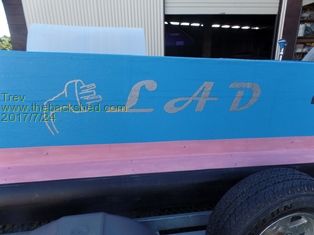 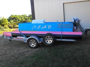 Time for a test. We headed off to Kinchant dam. Of course I towed it with my EV Hilux. The Golden Motor 10kW outboard is a very nice motor. The motor has a fair bit of weight, but I don�t know, a comparable petrol outboard may be similar weight. Two people on board, I am in the back. I am not much weight but still all adds up. The more power on, the deeper the back of the boat sinks, therefore creating more drag. 14.5A � 7km/hr 19A � 6.1 km/hr 32A � 7.8 km/hr 56A � 10.5 km/hr 82A � 12 km/hr 125A � 15 km/hr 182A � 17.5 km/hr 186A � 18 km/hr Notice at 14.5A the boat achieved a better speed than at 19A. The motor did not dig the back of the boat down so much and was able to achieve the higher speed. I moved to the front to help level the boat even more and the speed increased to 7.8km/hr at the 14.5A. Measured pack voltage at 52.6v or 3.28-3.29v per cell. With 3 people on board (Grandad, Son/Dad & Son) at full throttle (186A), 17km/hr. That�s 1km/hr slower with the extra 40kg. I tried to match the 14.5A but the closest I could get was 15A and the speed was measured at 5.5km/hr. When I moved to the front (balance the boat better) the speed rose to 6.0km/hr. It would be interesting to see what speed we could achieve at full throttle and the boat more level, but I didn�t want to leave the tiller steering at full throttle. We swapped the motors. Golden Motor removed, we put on the little pod motor that I tried with our solar canoes. This is the results with the pod motor. All 3 of us still on board. 8.2A � 6.3 km/hr 12.3A � 6.5 km/hr 17 � 7.8 km/hr 31 � 10 km/hr (full throttle) So it is obvious that the little pod motor is more efficient, that is, better speed for the amount of current or less current for the same speed. But of course the maximum current I could achieve was only 31A. The Golden motor has a lot more power. 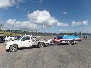 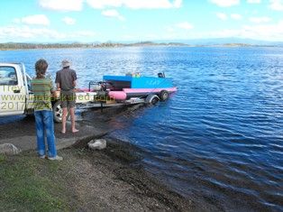 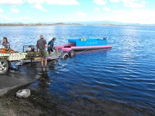 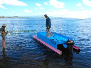 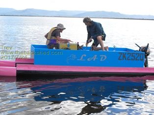 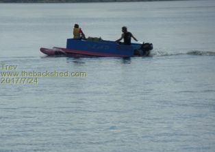 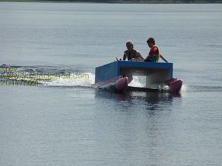 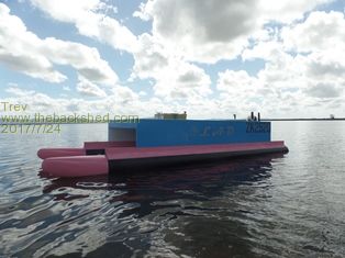 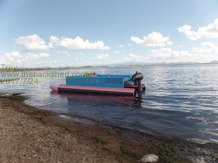 Trev @ drivebynature.com |
||||
| Boppa Guru Joined: 08/11/2016 Location: AustraliaPosts: 816 |
Judging by the photos and your description of the back sinking as you increased power, there should be a 'trim' adjustment usually between the bracket that bolts/clamps to the boat and the motor itself, it sounds like the motor is angled too high and needs to be dropped ie trimmed in (basically the prop moves closer to the boat and the axis of the prop is lowered more to the horizontal) The adjuster is usually a series of holes that you select the angle and push the pin in to hold the motor at that angle The trim will make a massive amount of difference to your speed and 'fuel' consumption so I would expect to see the speed increase for the same amps correctly trimmed |
||||
| Trev Guru Joined: 15/07/2006 Location: AustraliaPosts: 676 |
We get back to experimenting with boat concepts again. The idea eventually is to have 3 pipe lengths on each side. Recently tested a new motor, but had 2 pipe lengths on each side. Total length with 2 pipe lengths is 9.4m long. This is the new pod motor and old pod motor. 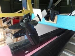 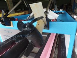 The old pod motor is the one that I tried with the original testing with canoes 2 years ago at Ankara, Murray river. The vertical round stainless steel pipe on these motors is hopeless because the water hits the front of the stainless steel pipe and creates an air pocket at the back, down to the propeller and cavitates. The new motor we used pvc to create a small foil. This foil did work some but needs to be longer. It still developed the air pocket. The cav plate did help but also needs some work too. The old pod motor we used ice cream container bent around a bit of plastic decking material cut to shape. This foil and cav plate works well. The new pod motor is definitely a stronger motor. My Dad and I set up the 2 lengths of pipe in the car park to the boat ramp. And then to launch it. I didn't get a photo of what it looked like after we took out the timber boxes as props for assembly, but the trailer at less than half the length of the boat, the pipe sagged plenty and almost touched the ground. 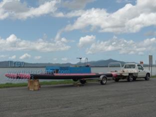 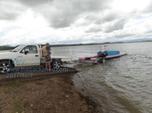 Once in the water is seemed to be very stable, and very good buoyancy. 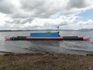 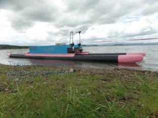 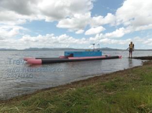 The data of power to speed as tested with this 2 pipe lengths boat. Boat driven cross wind. Battery voltage, 53v. The new pod motor. Amps Speed km/hr 7.7 7.2 13.2 9.2 16 8.8 19 10 25.5 9.8 (strange result) 45 11 up wind 16 8 down wind 16 9 The old pod motor, cross wind. 7.5 6.3 10.5 7.2 up wind 16 7.5 down wind 16 9.1 This data shows the new pod motor to be a little more efficient, but nothing real significant. The boat rides very smooth in choppy water. Trev @ drivebynature.com |
||||
| Trev Guru Joined: 15/07/2006 Location: AustraliaPosts: 676 |
We have also set about making another pontoon shape. Plastic coated timber was used for the temporary mold. Made one pontoon and filled with foam. 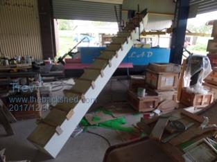 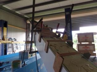 Today we laid the first layer of glass in the mold for the second pontoon. 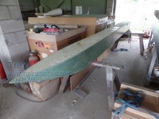 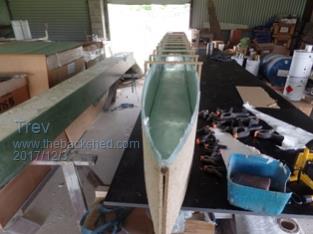 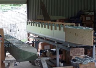  Trev @ drivebynature.com |
||||
| Trev Guru Joined: 15/07/2006 Location: AustraliaPosts: 676 |
Middle section is now complete, ready to put the pontoons on, but a little more patching of some holes in the top of the second pontoon to do, before that can happen. I need the top of the foam to be flat because the top will just have a fibreglass skin straight on the foam. 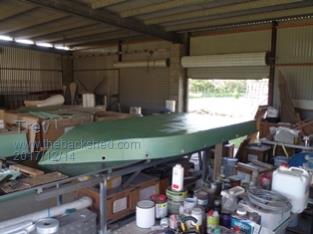 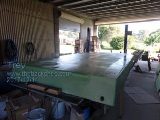 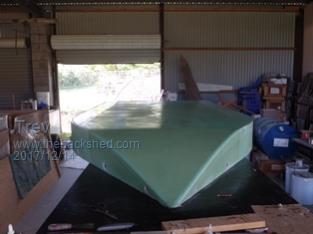 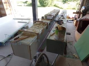 Trev @ drivebynature.com |
||||
| brucedownunder2 Guru Joined: 14/09/2005 Location: AustraliaPosts: 1548 |
Very interesting Trev. Did some fibreglassing way back in the 80-s when I was into skiff sailing .Q cells were the new idea for shaping those days ,light as a feather and easy to sand,shape. Anyhow ,following your progress-guess it's finished by now ,lol.? A late Merry Xmas to you and family and a happy ,safe new year . Bruce and Ilda Bushboy |
||||
| Trev Guru Joined: 15/07/2006 Location: AustraliaPosts: 676 |
Thanks for the wishes Bruce. Happy new year to you and Glenn and all the viewers. May this be a great year for you all. Yes Bruce I need to update the pictures hey. Here we go.......... 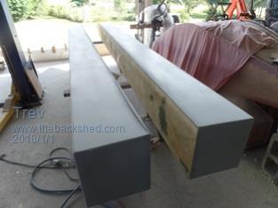 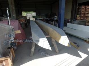 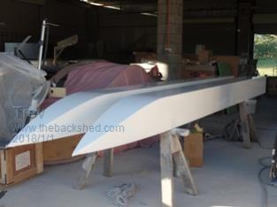 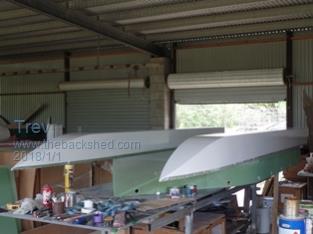 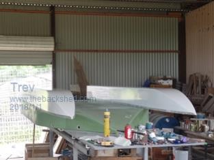 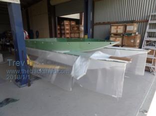 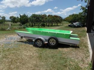 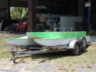 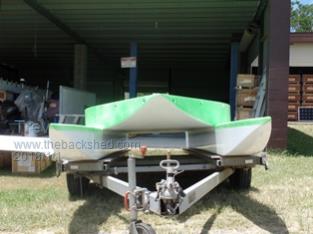 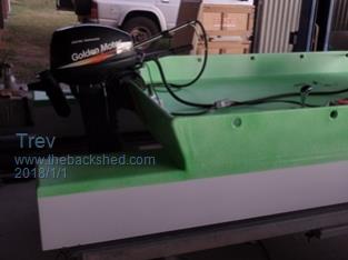 Trev @ drivebynature.com |
||||
| Boppa Guru Joined: 08/11/2016 Location: AustraliaPosts: 816 |
Happy new year Trev, boats looking good. Be interesting to see the performance figures against the older pontoons Those batts are bloomin great, they are outlasting a pair of 120ah LA,s for the fridge, amazing how much power they pack into such a small package |
||||
| Trev Guru Joined: 15/07/2006 Location: AustraliaPosts: 676 |
Rego done (the day after Christmas, after boxing day) and number painted on. Had lots of family here over Christmas / New Years and many named it Kerme (the green frog) so that's the name on the side. Headed off to the water. Of course in my EV Hilux. This Electric Hilux is my primary vehicle, it goes everywhere. My younger brother and his wife took these pictures. Good balance sitting still in the water. No performance numbers. This is like a bath tub. It filled up with water very quickly, drenched all my electronic gear. Dad's tape measure stuffed, and my multimeter don't work anymore. I haven't tried to switch anything else on yet. Flotation is excellent, with all the extra water, no problem, it cannot sink. The water runs out the 2 big holes in the transom. Going by feel. The boat probably goes a little better than the pipe, but nothing significant. It plows a lot. Very good in the waves from the other boats around us. Very stable and smooth. Cuts through the waves very easily. But could not get up on the plane. The electric outboard is a 20HP, so no spare power available. We had a little fun driving it around. It can pull a knee board but a bit slow. Back to the shed to think how to make it better. We have been working on it, but I will post again another time. 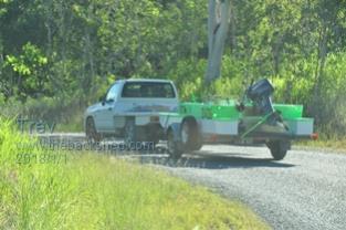 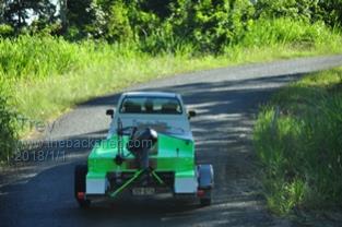 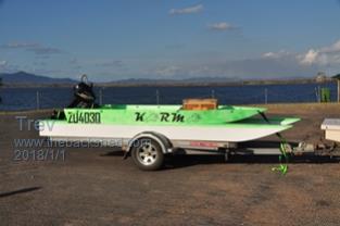 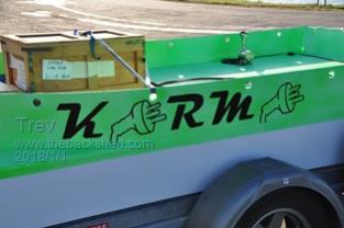 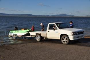 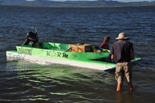 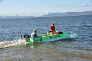 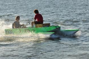 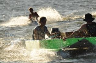 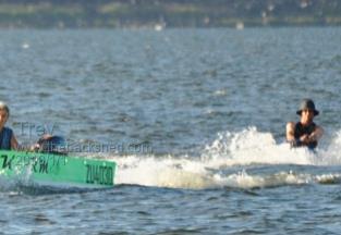 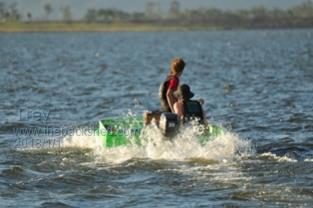 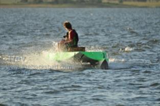 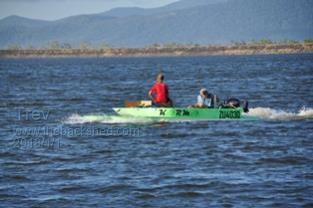 edit: just had to fix one picture Trev @ drivebynature.com |
||||
| Trev Guru Joined: 15/07/2006 Location: AustraliaPosts: 676 |
We added another pontoon width to each side. We made the front inside of the pontoon straight to reduce the funnel effect channeling water through the tunnel. The water through the tunnel was about 50mm lower than before. Left the top of the added section open at the front, just wanted to test the extra planing surface before we finished it off. The water spray over the bow was much better, a lot less. The open top of the new section did not take on any significant amount of water either. The water over the transom (motor mount) was no different, the water though the tunnel still hit the outboard leg and shoots up over the transom (motor mount board). It can't sink, the water just runs back out the holes. Next is to lift the motor higher. The boat was definitely faster with the double pontoon. It felt like it was getting up on the plane. The pontoon transom cleared of all water at 11km/hr and 61A, battery voltage 52v. Speeds and currents. 4km/hr 12A 6km/hr 23A 10km/hr 54A 11km/hr 61A 14km/hr 95A 18km/hr 128A 22km/hr 189A 24km/hr 191A 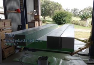 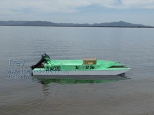 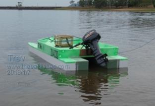 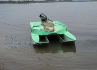 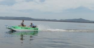  Trev @ drivebynature.com |
||||
| Trev Guru Joined: 15/07/2006 Location: AustraliaPosts: 676 |
We lifted the motor mount by 180mm. Just made a temporary ply board. By the time we got to the water, the ply had a crack both front and back, so did not risk going in the water. We removed the motor and ply for the trip back home. Fitted some steel angle to support the ply. Then off to the water to again to test. The cav plate was level with the surface of the water at rest, which turned out to be too high. As soon as power was applied, the prop cavitated. We did manage to get it up on the plane once by going around in circles to increase the water level in the tunnel. No speed record, the GPS was flat. 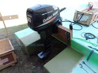 So we cut 50mm off the top of the ply and went to the water again. Speeds and currents are better, but not significantly different to before. Gained 1km/hr top end speed. Speed and current 5.2 km/hr 10.3A 6.6 km/hr 15.1A 7.6 km/hr 21.8A 9.7 km/hr 42.9A 11 km/hr 52A 14.1 km/hr 93A 17.2 km/hr 123A 19 km/hr 150A 25 km/hr 189A 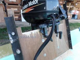 Trev @ drivebynature.com |
||||
| Page 1 of 3 |
|||||
| The Back Shed's forum code is written, and hosted, in Australia. | © JAQ Software 2026 |
