
|
|
Forum Index : Microcontroller and PC projects : Transistor bases in parallel....
| Author | Message | ||||
redrok Senior Member Joined: 15/09/2014 Location: United StatesPosts: 209 |
Hi djuqa;I don't understand? I mostly use MOSFETs for the reasons I suggested.I generally don't like bipolar transistors because they tend to have higher on state voltages, require drive current, and tend to have less current capabilities in the same package as MOSFETs. I often use MOSFETs in power applications where I can use, say a 30 amp part, in a circuit that switches, say 5 amps. Heavily de-rating the part allows me to not bother with a heat sink. You can't really do that with a bipolar transistor because there is always a significant voltage drop from collector to emitter. Even at 5 amps you still need a heat sink. I make Solar Trackers and use a 50 Amp PSMN017 MOSFET in an H-Bridge motor driver. I don't use a heat sink yet effectively drive large linear actuators. I couldn't come close to doing this with a bipolar design. redrok |
||||
Grogster Admin Group Joined: 31/12/2012 Location: New ZealandPosts: 9931 |
@ redrok: djuqa was having a dig at MY not using them.  My company logo - which just recently became a registered trademark of Rictech Ltd - is a depletion-mode MOSFET.  Well, it is a "Depletion-mode P-channel MOSFET with external substrate connection". I just loved the look of that symbol, so my graphics designers for the website custom-created that logo, which I still love. Well worth the graphics designers fee, and I now "Own" that logo having just succeeded in registering it as a trademark, so I have no fear of MOSFET's really. djuqa is correct though - I should use them more and learn about them more, and start to put the bi-polar transistors back up on the shelf. Well, it is a "Depletion-mode P-channel MOSFET with external substrate connection". I just loved the look of that symbol, so my graphics designers for the website custom-created that logo, which I still love. Well worth the graphics designers fee, and I now "Own" that logo having just succeeded in registering it as a trademark, so I have no fear of MOSFET's really. djuqa is correct though - I should use them more and learn about them more, and start to put the bi-polar transistors back up on the shelf.  Smoke makes things work. When the smoke gets out, it stops! |
||||
| JohnS Guru Joined: 18/11/2011 Location: United KingdomPosts: 4298 |
Anyone have any links for "instead of transistors here's how to use MOSFETs" type things? MOSFETs for (a bit more than) dummies. Or beginners to advanced practical MOSFET circuits. And perhaps when not to use MOSFETs (if this means anything useful). John |
||||
Quazee137 Guru Joined: 07/08/2016 Location: United StatesPosts: 603 |
Looking at the data sheet they only need 33.3mA and at 135 ohm. There isn't much to kick back. I have seen old modems driving these type with tiny logic chips. One that I traced out was like this. I added the leds  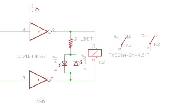 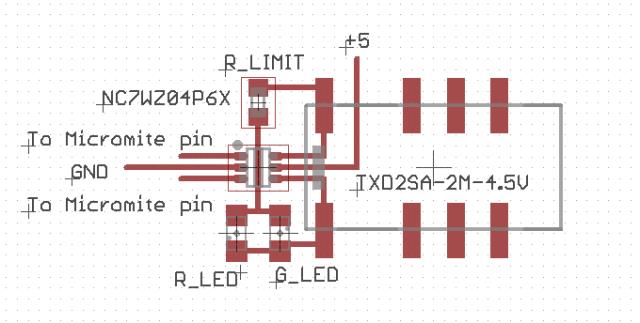 and  Funny how you hit on something I have going on the back burner. I'm working on a circuit that can operate a ball valve where a pulse will open and the next pulse will close. With 4-20 feed back to a PLC. |
||||
| CaptainBoing Guru Joined: 07/09/2016 Location: United KingdomPosts: 2171 |
Here is an excellent primer: http://www.talkingelectronics.com/projects/MOSFET/MOSFET.html |
||||
| JohnS Guru Joined: 18/11/2011 Location: United KingdomPosts: 4298 |
Many thanks! John |
||||
| Quazee137 Guru Joined: 07/08/2016 Location: United StatesPosts: 603 |
Thanks for getting this on the front burner. Here is what I am bread boarding up. 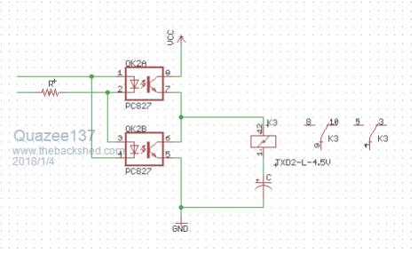 Just have to remove the relays off a few boards to test. Quazee137 |
||||
| redrok Senior Member Joined: 15/09/2014 Location: United StatesPosts: 209 |
Hi Quazee137; Well there is the 33.3mA. This has to go somewhere. In this case it will pass through the output MOSFETs on the gate. Since the NC7WZ04P6X is a normal gate, (Without Tristate), one of the two outputs in each gate will always be ON. This circuit is essentially a full-bridge. OK, I see what you are trying to do here. 1. Pulse HIGH to switch the relay one way, and charge the capacitor. 2. Pulse LOW to switch the relay back, and discharge the capacitor. There is a problem though: This opto-isolator doesn't have any catch diodes across the NPN output. I would suggest adding 1N4148, or the like, to direct the kickback current to the supply rails.This should work fine, assuming the 2 diodes are added. redrok |
||||
| Grogster Admin Group Joined: 31/12/2012 Location: New ZealandPosts: 9931 |
Interesting posts here chums, keep them coming. I am reading them all. Smoke makes things work. When the smoke gets out, it stops! |
||||
bigmik Guru Joined: 20/06/2011 Location: AustraliaPosts: 2979 |
Hi Quazeee, How are you expecting to drive the Opto's? The only way I can see that cct working is if you use 2 IO pins 1 high and one low and switch polarity of both when you want to trigger the other Opto. Regards, Mick Mick's uMite Stuff can be found >>> HERE (Kindly hosted by Dontronics) <<< |
||||
| redrok Senior Member Joined: 15/09/2014 Location: United StatesPosts: 209 |
Hi Quazee137; Here is your circuit with a current amplifier half bridge. 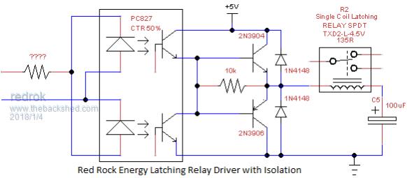 The problem with your first version is the OptoIsolator requires much to high of a drive current to properly switch the relay. The PC827 has a CTR, Current Transfer Ratio, of 50%. This one has a current booster so maybe only 5mA of Opto drive is required. I also added the catch diodes. The optional 10K resistor assists in fully charging and discharging the cap. There is one quirk with this circuit. Unlike my 2 capacitor circuit, above, which fully charges the capacitors even with no drive applied this circuit leaves the capacitor free floating when no drive is applied. So if the capacitor has some leakage it might self discharge. The solution is to send a dummy, or redundant, switching action the same as the last action performed before switching to the new position. Have fun!!! redrok |
||||
| Quazee137 Guru Joined: 07/08/2016 Location: United StatesPosts: 603 |
Sorry left out that the Valve has a cam with adjustable switches. I have 3 switches doing the 4mA valve is closed, 12mA valve is in transition and 20mA valve is full open. Then a few more giving me steering logic to feed the relay driver. I am getting one from a system that is offline for a few months. And having one to tinker with may change how I do this. Hands on is the best teacher and it stays with you. Yes resending the last state was to be done so hardware and software always on the same page. A few more ways to play with this. 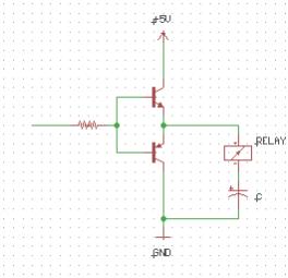 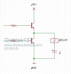 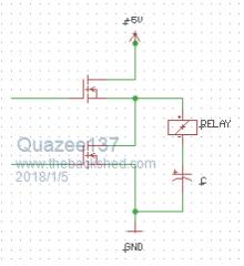 The lowest leakage film caps are Teflon (PTFE) or Polystyrene (PS). The next best would be polypropylene (PP). Don't use Polyester/Mylar (PET). 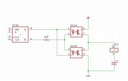 I have this on a bread board and looking with scope. switching every few minutes. The cap seems to be absorbing any kick back from the relay coil. Fun stuff Quazee137 |
||||
crez Senior Member Joined: 24/10/2012 Location: AustraliaPosts: 152 |
If you only switch after the relay current has decayed to 0 then there will be no kickback. However I'm a bit uneasy about a design where a software glitch can damage the hardware. I would add two diodes. |
||||
| flip Senior Member Joined: 18/07/2016 Location: AustraliaPosts: 119 |
If you want to do it with only one output you could have 2 opto diodes in parallel (one reversed of course) and run with a series RC from uM output (other side of opto-diodes are connected either to +ve or -ve -doesn't matter, and uM set high or low on power-up routine. Assume 3.3V supply,2.1V across opto and 5mA required to turn on opto, and 10mS pulse required for relay gives following calculations. V=3.3-2.1 = 1.2V Ipeak=2*5mA=10mA R=1.2/10mA = 120ohm t=RC....or C=t/R....C=10/.12 uF =100uF should do it Series capacitor means zero DC current consumed (if left on or off) Assuming these are pulsed (latching) relays If 10mA or more is required it may be pushing output current limits, is so use BC108 +BC158 or similar TUN/TUP (cheap NPN/PNP) pair with collectors to rails (NPN to +ve, PNP to -ve) emitters commoned and connected to RC (with a smaller resistor) bases commoned and connected to uM Regards, Phil |
||||
| redrok Senior Member Joined: 15/09/2014 Location: United StatesPosts: 209 |
Hi GrogsterYes you can! However, you need to use the 100uF cap as the 33uF didn't quite have enough energy storage, but the 100uF did. I also did it with 3 relays in parallel. You asked if there is any damage to the transistor discharging the cap. For fun, I did an experiment and charged/discharged a cap 1 million times. I used 1K, 100uF, and a voltage of 17.3V, and discharged 10 times per second. I could see no determent on either the 2N7000 nor the 2N3904. Have fun!!! redrok |
||||
| Quazee137 Guru Joined: 07/08/2016 Location: United StatesPosts: 603 |
The relay I pulled of a Telcom board is only pulling 6.5mA and may be a 3volt coil. It is working on the bread board. My Granddaughter reminded me that we had made line follower bots when I had my Preschool/Day care. The kids had such fun using dry erase markers on the tile. I went in my many (junk) boxes and found a few. I did not find the paper work. But did google and found this. 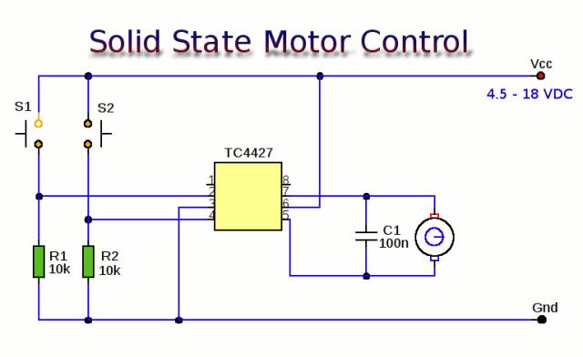 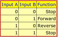 and that lead to me using this. 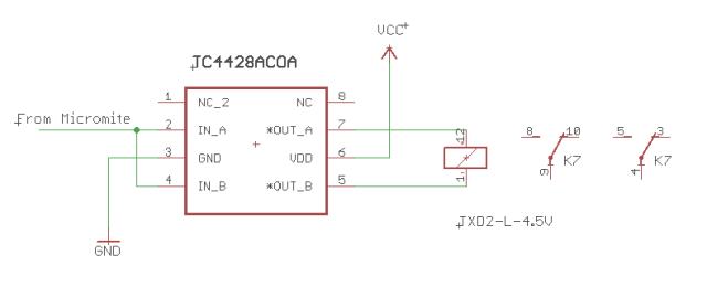 I'll be using a different relay. Now just waiting for the valve to show up and start playing with it. Quazee137 |
||||
| The Back Shed's forum code is written, and hosted, in Australia. | © JAQ Software 2026 |
