
|
|
Forum Index : Microcontroller and PC projects : MM2 Keypad Encoder...
| Author | Message | ||||
Grogster Admin Group Joined: 31/12/2012 Location: New ZealandPosts: 9932 |
I often need several buttons or a small matrix on my projects. While the MM has the nice KEYPAD command, it does gobble up a lot of I/O pins in the process. I often found that once I had designed all the other things in, there simply was no I/O pins left for even a small matrix. I had that problem with the latest controller board that uses a 44-pin QFP MM2 chip, but there was just not going to be enough pins left to service the keypad. There is the 'Buttons on a single ADC pin' idea, and that does seem to work reasonably well for a few buttons, but if you need more then ten it starts to become difficult to get reliable results. So, I rustled up this board, which is quite small at 39mm x 35mm, and allows for up to a 8x8 matrix as standard. It can directly interface to most 4x4 and 4x3 keypads using either the top or bottom rows of pins on the box-header, or you can design your own matrix up to 8x8 allowing for up to 64 buttons. 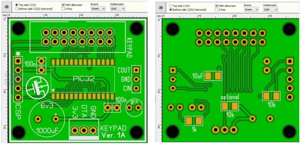 Output is via COM1, cos that's what I needed, but there is some logic to using a COM port for a keypad like this, cos when connected to another MM, it's native serial port buffer will hold the data for you, and all your main code needs to do, is check if there is anything in the buffer and act accordingly. The buffer will catch any key-press, even if the main code is busy with something else at the instant you press a key. Within the keypad MM code, if you are using a 4x3 or a 4x4 keypad, you can connect that and use MMBASIC's built in KEYPAD command to scan the matrix, and just output the serial data you want via something like SELECT CASE KEY and CASE routines, or for a bigger matrix you would need to write something of your own. The LED on pin-14 can be made to blink whenever it sends something out on the serial port. Most commercial keypads have an inherent resistance of about 150-200 ohms per contact, so that is why I don't have any series resistors on the matrix pins. If you felt you needed series 1k resistors, that would be something you would have to fit externally. If there is any interest in this board, I will put up a constructors pack on my website and add a link here. Currently, you can get ten of these boards made for US$5 at PCB-GOGO..... Smoke makes things work. When the smoke gets out, it stops! |
||||
| robert.rozee Guru Joined: 31/12/2012 Location: New ZealandPosts: 2499 |
another candidate for this sort of thing may be either of these: MCP23017 (nz$1.20ea) http://www.microchip.com/wwwproducts/en/MCP23017 MCP23018 (nz$1.50ea, open drain outputs and 5v tolerant) http://www.microchip.com/wwwproducts/en/MCP23018 both ara available in SOIC and SPDIP, providing 16 general-purpose I/O lines, along with a whole load of interrupt configurations to signal input changes back to the host. note: the 23017 and 23018 have different pinouts. it looks like the 23018 may be a slightly later device, but it lacks push-pull output drive. cheers, rob :-) |
||||
bigmik Guru Joined: 20/06/2011 Location: AustraliaPosts: 2979 |
Hi Grogs, All, Sometime ago I designed my I/O Panel that used one IIC channel (2 wire circuit) to drive an LCD panel, 4x4 keypad, 8 LEDs and 8 general IO pins... based on cheap PCF8574 chips (about $0.70AUS) . These chips can also trigger an interrupt to tell the main micro that a key has been pressed.. Whilst I probably won’t get this board redone I stilll have 4 or 5 boards left at $6ea.. but as there is nothing much to the circuit (see section 2 of the schematic in the link above) just copy that part of the circuit.. program description on how it works is in the manual. Of course that uses IIC instead of Grogster’s comm port but as it provides an interrupt it might be an interesting alternative. Regards, Mick Mick's uMite Stuff can be found >>> HERE (Kindly hosted by Dontronics) <<< |
||||
| The Back Shed's forum code is written, and hosted, in Australia. | © JAQ Software 2026 |
