
|
|
Forum Index : Microcontroller and PC projects : E-28 to Nano Pinouts.
| Author | Message | ||||
| Phil23 Guru Joined: 27/03/2016 Location: AustraliaPosts: 1667 |
Just wondering whether a pin remapping adaptor would be useful in some instances, like taking PCB's designed to accept a Nano & use an E28 in it's place. Basically it would just need two rows of 15 pins on each side, & the traces to remap them. 1st & 3rd row could accept the E28, & the 2nd & 4th provide the Nano output pattern.  There's quite a few interesting projects out there with PCB's available that accept either Uno's or Nano's. The ones that rely on Uno's should be easily ported with a CGMicroboard2, but the ones that use Nano's couldn't directly accept an E-28. Does it sound at all useful? Phil. |
||||
| RyanHammond Newbie Joined: 29/03/2018 Location: United StatesPosts: 15 |
Does it sound at all useful? YES, IT DOES! |
||||
| Phil23 Guru Joined: 27/03/2016 Location: AustraliaPosts: 1667 |
Not sure how the setpin page ended up in that post, as I didn't actually get to finish it. I was having problems posting yesterday, couldn't seem to upload images, so linked to the CGMicro one from a previous post. Tried to upload the Nano pinouts for graphical comparison, but it just hung, so tried a link from google images, and found that when I hit post it just hung. Pasted in & out numerous times & then abandoned the post. Seems it made it up in some form after all. Phil |
||||
Azure Guru Joined: 09/11/2017 Location: AustraliaPosts: 446 |
I was a bit confused how it related to the pinouts, now it makes sense. I think that pin layout diagram is great, what was it done in? |
||||
Grogster Admin Group Joined: 31/12/2012 Location: New ZealandPosts: 9934 |
The issue I see with this, is that weather you had the extra row of pins on the inside or the outside of the E28, the footprint would still be wrong for the Nano add-on boards then. Perhaps I am missing something? Because the E28 is designed to be the same size as a Nano, there is no room to move either side.  Perhaps you could do this with narrow little PCB's where you had female strips at the top, and male strips at the bottom, and the remapping on the little PCB's. Like this:  That would stand tall though, and personally, I think it would look a little ugly. Smoke makes things work. When the smoke gets out, it stops! |
||||
| Phil23 Guru Joined: 27/03/2016 Location: AustraliaPosts: 1667 |
It would need to be at least 0.1" or so wider. So it was a single board that sat underneath the E28. E28 sits on top, the 2 rows of Nano pins stick out the bottom, both to say the right of the E28 row. Remapping on double sided PCB should be doable. My CAD representation....  It could use pins & sockets, or just joined with pins like Rob's Nano ASCII programmer, which would ne neat, but jut a bit wider in overall width. Phil. |
||||
| Grogster Admin Group Joined: 31/12/2012 Location: New ZealandPosts: 9934 |
Oh, I see what you are getting at.  How would you map the E28 pins to the Nano? IE: Which pins on the E28, would you want going to where on the Nano? Smoke makes things work. When the smoke gets out, it stops! |
||||
| Phil23 Guru Joined: 27/03/2016 Location: AustraliaPosts: 1667 |
The CGMicroboard2 seems to pick up what's compatible. But in the case of E28 Vs Nano, first ones to visit are Power/Gnd, Tx/Rx, I2C & the other thing... SCL/SDA. The rest just need to be A or D capable according to the Nano Map. Notice also that the Nano has 30 Pins. Reset & Gnd are on both sides.  |
||||
| Grogster Admin Group Joined: 31/12/2012 Location: New ZealandPosts: 9934 |
Hokey pokey, leave it with me. I will see what I can rustle up in the next few days. Updates will be posted here for your comments. Smoke makes things work. When the smoke gets out, it stops! |
||||
| Phil23 Guru Joined: 27/03/2016 Location: AustraliaPosts: 1667 |
I should mention the motive behind my thoughts. Been looking at Madness's Charge Controller board over in the Electronics forum. Thinking I'd like to be able to drive those Mosfets with a Micromite. Cheers Phil. |
||||
| Grogster Admin Group Joined: 31/12/2012 Location: New ZealandPosts: 9934 |
This is what I have so far:  Not all of the Nano pins can be mapped to the E28, but I HAVE mapped the SPI port, the I2C port, COM2 and the console. Pins marked as ADC are MM ADC pins. Pins marked as PB/PC etc are just standard I/O pins. I will make up a proper pin map spreadsheet chart thing once you are happy with what we have. Smoke makes things work. When the smoke gets out, it stops! |
||||
| Phil23 Guru Joined: 27/03/2016 Location: AustraliaPosts: 1667 |
I think I noticed that you might come up a couple of pins short. First thought I had was skipping the high number in A0 to ... & D0 to .... But then thought some of those high number might have other significance, like SPI Coms etc. I'm sure you thought the same. Phil. |
||||
| Grogster Admin Group Joined: 31/12/2012 Location: New ZealandPosts: 9934 |
Is this the sort of thing you are after though? Can you see any obvious changes you would like made? Smoke makes things work. When the smoke gets out, it stops! |
||||
| Phil23 Guru Joined: 27/03/2016 Location: AustraliaPosts: 1667 |
Hi Grog, All looks pretty good to me. Looking about there's a swag of PCB's out there designed to serve a purpose & controlled by a Nano. Most look like they could also be driven by basic. Usually their pin usage count from the Nano is fairly small so the few missing ones in the conversion shouldn't count. I did briefly think that maybe just a 28 pin DIL on a Nano foot print board was an alternate solution, but there'd be no space for the 1455 & USB would be lost; ant that direction would essentially be designing an new alternate Micromite. Just remapping the E-28 seem a much more sensible solution. Cheers Phil. |
||||
Quazee137 Guru Joined: 07/08/2016 Location: United StatesPosts: 603 |
I was looking for parts on www.banggood.com to see if prices had changed on a few items I got last year. I found this that may be of use to E28 users. And remembered this post. 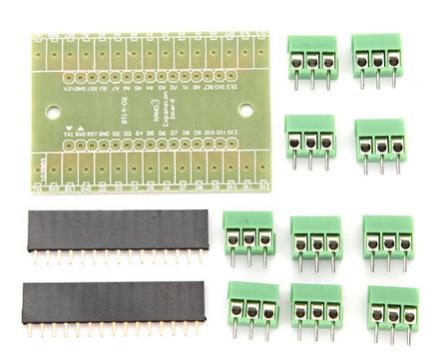 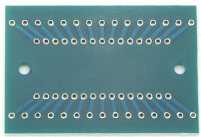 I had picked up a few of ones like these but thay had the Ground pads tied where these are nicely just raw point to point. A fast way to make use of an E28. |
||||
CircuitGizmos Guru Joined: 08/09/2011 Location: United StatesPosts: 1427 |
 Micromites and Maximites! - Beginning Maximite |
||||
| The Back Shed's forum code is written, and hosted, in Australia. | © JAQ Software 2026 |
