| Author |
Message |
plover

Guru

Joined: 18/04/2013
Location: AustraliaPosts: 306 |
| Posted: 02:42pm 08 Jul 2018 |
 Copy link to clipboard Copy link to clipboard |
 Print this post |
|
Geez, I started a new voluntary job helping a research group, for this I am doing crash course in DEX and some switchmode power supply design stuff. Ever since I started I have been thrown an increasing string of challenges that makes me wonder what I have triggered.
Ok, one thing that happened yesterday, I was organising content of some big hard drives, sorting out kategories in an effort to free up a spare drive for testing why my Windows install no longer will connect to my modem on ethernet. Long story and I am digging in.
Have two USB3 drive carriers plenty of USB3 ports on two hp8300 SFF Elite models, obtained recently. One for me and one for my wife. Time came to make a security back up as well for both just in case.
Backed up my machine, after hours of organising files on the two External USB3 drives. By the way speed from 135 MB/s to 170 MB/s real pleasure to move 100 dreds of GB in reasonable time. Half a day and I turned off the power to my machine, moved one drive carriers to the other PC, what do you know, not working at all.
Because it had worked minutes before, I ignored my immediate thought " oh,no the drive carrier is dead" well I should not have ignored this unscientific response. After an hour I had to admit the box was dead. Out came the pcb for further investigation.
I decided that since I am doing this crash course in DEX operation I will use DEX to do documentation from the beginning and some other exercises with graphics and 3D, including recording photos in DEX. It may come down to drawing a schematic but hoping not.
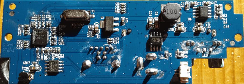
A.. Using USB microscope I managed to get main component ICs identified, later a friend suggested using my smartphone as well and test various lighting arrangements. I am not much good on photography but it turned out that the smart phone idea was good.
On the board there is a Winbond 25X20CL VIG. Serial Flash memory. I have datasheet for 25X20CLSVIG, that is and S in front of the VIG. On my board there is definitely no S and I did not find any datasheet for "25X20CL VIG" my question is there any one with some working knowledge of such critters?
Until 2 days ago I did not even know of SPI (eeprom ?) memory chips but I thought it was on the Backshed that I read about somebody programming these or had just started programming SPI memory, it stuck in my head because I had never noticed those before.
The important thing is that of late memory eeproms have been in my mind.
I very interested in how to read/write these serial eeproms. When I saw this Winbond I was reminded of others waiting for my attention.
B.. I have a very expensive older Labtop with a graphics card where I would like to read/wrie the serial eeprom (replace if needed), and also the serial eeprom in the BIOS.
Have been meaning to do that for some years. I have collected bits, spare chips, carrier boards and test boards even some cheap eeprom readers from ebay and if needed a pickit 3 board. Then along came MMBasic etc
Now is a good time to pick up on handling serial eeproms and I expect this would be simple using MM, as I have a couple of Micks 28 pinners already tested and working. that is a far as it has got.
I have some display panels too I think one was for a use in a "backPack" arrangement, I probably had in mind that this might be the way to make a stand alone simple programmer/reader but a bit optimistic on my part. Seems like a good idea for me to stay with a simple USB tethered MM using a linux terminal.
Most likely I have missed important developments and much of this has already been posted?
Any advice an pointers in general welcome to start me off and try to stay focused as best I can. If there is anything on ebay already doing simple reading/writing of serial eeproms I am interested to here.
C.. It is not the first time I have tried reverse engineering with generous help of photographs and graphics programs like PhotoShop and its linux equivalent.
One thing I have missed for a while is simple photographic equipment that can take good pictures. I had a good setup, see later.
As mentioned I have USB microscope which is great for smaller pictures but 10x10cm is probably stretching the use. Three problems the lighting control I find too course for the built in lights and it is too unstable on its small stand. The focus control is not good, too course and with plenty of backlash.
Something like a small camera with pc software controlling and collecting snaps. I had that with my Canon Power Shot A70, works well, did work well. The camera belongs to a class of lemon cameras, problem acknowledged by Canon.
In my case the imager and associated circuit has been repaired twice (under normal and extended waaranty), but now it is dying. Needs serious incantations to coach it into working for short periods.
Anybody got suggestions for camera/phone eauipment that can be used simply and easy.
D.. It is my plan to try and follow up with some pictures and DEX work as I gain experience. I am going to attach a photo from my smartphone, 5 times magnification can be applied and apart from the lighting in this case is such that uneven result over the board.
What I am more interested in if anybody has suggestions for software that can straighten out or just tweak the picture so it fits real square
The board comes from a SimpleCom SD323 unit and I have searched for the schematic but so far not had any hits, I am hoping when getting around to look at the circuitry for individual IC's that guesswork from reference circuits will give a good idea of the schematics, fingers crossed
Edited by plover 2018-07-10 |
| |
panky

Guru
Joined: 02/10/2012
Location: AustraliaPosts: 1120 |
| Posted: 10:30am 09 Jul 2018 |
Copy link to clipboard |
Print this post |
|
Your pic can straightened with either Photoshop or Gimp using warp or distort functions.
Clarity on the board could be improved by first cleaning with a flux remover and then useing multiple light sources to remove shadows. Use contrast, brightness and curves to even out lighting and finally, some unsharp masking to improve the edge sharpness.
panky
... almost all of the Maximites, the MicromMites, the MM Extremes, the ArmMites, the PicoMite and loving it! |
| |
plover
Guru
Joined: 18/04/2013
Location: AustraliaPosts: 306 |
| Posted: 12:23pm 09 Jul 2018 |
Copy link to clipboard |
Print this post |
|
panky
Thanks for posting. I will get something done about a camera holder for my smartphone and lighting. I agree about the cleaning but time and risk of wiping out the prints while not too big in this case has me reticent about cleaning.
The two programs you mention I have used once a year for some layered photographic work but I find I do not use it enough, I forget and spend too much time figuring out what is where. Am hoping that perhaps there is something simpler.
One thing I am hoping for is whatever camera and software I may come across will have curvature correction as a simple click built in.
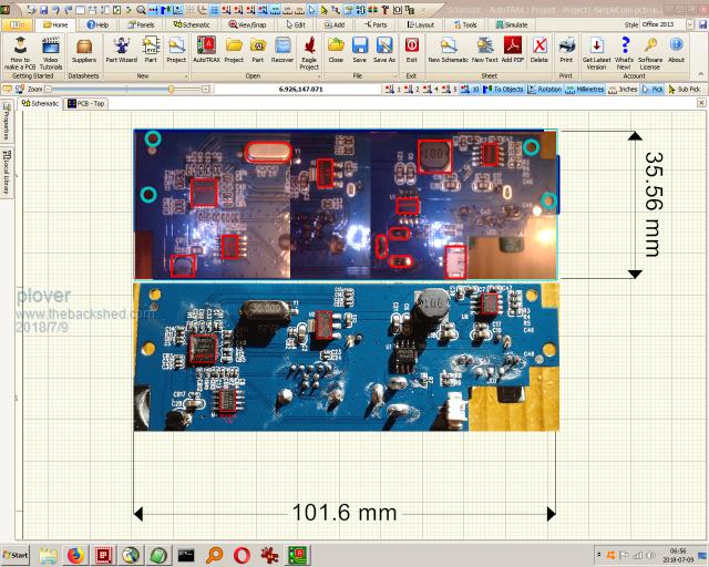
I am attaching a snap of the DEX experiment on the board. Top one was my first rushed go to get identification on the way. For this I am happy as I managed to get id of the IC's and located on the board, so that in a day or two perhaps a week or longer, when I will have forgotten much, I can go straight to the record an try to pick up. Have datasheets and had a quick look.
On the smartphone picture, yes the shadows give away that lighting is bad, I am thinking of a ring LED lighting. My fluorescent ring light on the bench mounted magnifier blew ater short time for a second time so I replaced it with an Oyster kit and I am happy with it, not perfect as I have no intensity control. But I may get one more of those second hand from Oatley if still available. Approx 120 mm diameter from memory
Errrrhh, I did something wrong, I think I tried to upload a DEX program file, I meant to upload a snap. Now I can not upload pirtures, so I will have to wait.
Errrhh 2: when closing down I found a window waiting from TBS, and the penny dropped why I could not upload the picture. I can make an upload here it is.
 Edited by plover 2018-07-10 Edited by plover 2018-07-10 |
| |
plover
Guru
Joined: 18/04/2013
Location: AustraliaPosts: 306 |
| Posted: 06:42am 10 Jul 2018 |
Copy link to clipboard |
Print this post |
|
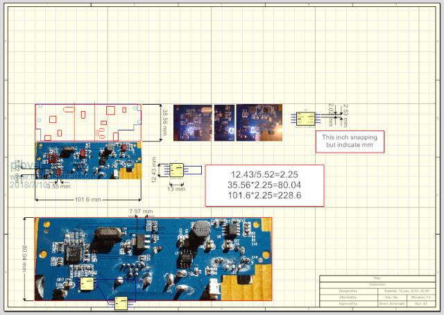
A bit more eperimentation with the images and precise distances used. Keep in mind only some conceptual thoughts are being tested in part.
I have moved one of the 'images' aside, so I have a 'silkscreen layout, there is a reason for that may become clearer later.
With the having a really good photograph I think I can place schematic symbols on top of the photo, then trace the pcb pattern to a degree, looks like I can get away with wiring runs from item to item.
Becoming clarer that I would benefit from being able to make som transparent behaviour to the imaged, so as to fade it away or just turn it on and off. Will se.
Have scaled the image to fit the symbol for a Winbond W25X20CL spi flash chip. I think I have pinned down the SPI flash chip.
W25X20CL SPI-flash
2.5 / 3 / 3.3 V
2M-BIT
SERIAL FLASH MEMORY WITH
4KB SECTORS AND DUAL I/O SPI
Edited by plover 2018-07-11 |
| |
