
|
|
Forum Index : Microcontroller and PC projects : DS18B20 keeps returning 1045 degrees?
| Author | Message | ||||
Grogster Admin Group Joined: 31/12/2012 Location: New ZealandPosts: 9933 |
Hi there.  This is odd. I have two 18B20 sensors(the TO92 ones), on 100mm leads, and one returns the correct temp, the other one alternates between the correct temp and 1045 degrees. 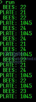 I have four sensors on the board, and two are not connected. I am using parasitic power. I have tried other sensors but get the same result. I am providing the 4k7 pull-up via a 4-way SIL resistor. 'BEES' sensor is on pin-17, and 'PLATE' sensor is on pin-18. 28-Pin MM, Firmware 5.04.08 The rogue result of 1045 is the same if I switch sensors, or change them for totally different ones.  Does anyone have any ideas as to what I might have done wrong? Perhaps I should power them directly do you think? (not via parasitic power) Smoke makes things work. When the smoke gets out, it stops! |
||||
| lizby Guru Joined: 17/05/2016 Location: United StatesPosts: 3733 |
I see you have a correct (reasonable) reading of Plate at some points--21. 1045 in binary is 10000010101. If you strip off that high bit, you have &B10101, which is 21. I don't know what this is telling us, but probably something. I have lots of DS18B20s and have never seen a reading like this, but I've also never used parasitic powering. PicoMite, Armmite F4, SensorKits, MMBasic Hardware, Games, etc. on FOTS |
||||
| Grogster Admin Group Joined: 31/12/2012 Location: New ZealandPosts: 9933 |
Yes, I get correct readings at some points, but totally wrong ones at other times. I've just checked the last PCB version that only had two sensors, and they were running on parasitic power, and they worked just fine. Same firmware, same 28-pin chip, and the two sensors I am playing with now are on the same pins as the previous version - I am just not connecting to the other two sensors at this time. I make no reference to the other two sensors in the code just yet, I am just trying to replicate what WAS working fine. Unless the 4k7 SIL resistor can somehow be responsible for this.... It is reasonably easy to hack the PCB and connect the sensors direct to the 3v3 supply rather then running them on parasitic power, but it worked last time, so I really did not think this would happen, and is a bit of a curve-ball!  I will hack the PCB for the two sensors I am trying to use, so they are powered directly from 3v3 and see if the temperatures come in correctly. Smoke makes things work. When the smoke gets out, it stops! |
||||
plover Guru Joined: 18/04/2013 Location: AustraliaPosts: 306 |
You did do an ohms check on the 4.7K resistor ? Not clear to me if you did. |
||||
| Grogster Admin Group Joined: 31/12/2012 Location: New ZealandPosts: 9933 |
Yes, I certainly did - before I installed it, to make sure it was a bussed 4k7 - and it was. I hope to try the hack out soon and see if they work better on standard 3v3 power instead of parasitic power. Smoke makes things work. When the smoke gets out, it stops! |
||||
| Grogster Admin Group Joined: 31/12/2012 Location: New ZealandPosts: 9933 |
OK, with a seperate 3v3 supply to the sensors, everything works as expected. I still have the 4k7 SIL pullup on the data lines, but now they have their own 3v3 supply, the temperatures are reporting correctly. Perhaps best to always use standard power and not parasitic.  Smoke makes things work. When the smoke gets out, it stops! |
||||
| lizby Guru Joined: 17/05/2016 Location: United StatesPosts: 3733 |
One possibility is that the combination of parasitic power, 3.3V, and 4K7 pullups is marginal. The Maxim datasheet shows a MOSFET supplying additional power when in parasitic mode, bottom of page 7: https://cdn.sparkfun.com/assets/4/a/8/8/8/DS18B20.pdf . That would seem to counter the simplicity of the parasitic powering. PicoMite, Armmite F4, SensorKits, MMBasic Hardware, Games, etc. on FOTS |
||||
| Grogster Admin Group Joined: 31/12/2012 Location: New ZealandPosts: 9933 |
Yes, indeed. From this point forward, I will use conventional power for these devices. What threw me, was it worked in the first version just fine, so I figured.... Very interesting. So it would seem that although parasitic power is possible, it is probably not to be recommended, as when the device does the conversion, parasitic power can be marginal. You learn something new every day.  Smoke makes things work. When the smoke gets out, it stops! |
||||
Chopperp Guru Joined: 03/01/2018 Location: AustraliaPosts: 1123 |
Rightly or wrongly, I have DS18B20s operating for a number of years now with 1k8 parasitic resistors for long runs with no apparent problems. Started higher & dropped the values until they worked. I think I have even been down to 1k5 on a 3V3 supply. The only thing that I was really worried about was the self heating of the device with the higher current through them. I haven't noticed a problem in that area. May be interesting to compare one of my long 2 wire connections with a 3 wire connection one day. I might even read the stuff on the link above ChopperP |
||||
| The Back Shed's forum code is written, and hosted, in Australia. | © JAQ Software 2026 |
