
|
|
Forum Index : Microcontroller and PC projects : Nucleo-L476 owners - please test
| Author | Message | ||||
| matherp Guru Joined: 11/12/2012 Location: United KingdomPosts: 11166 |
I did some more testing on the Nucleo-L476 and discovered that analogue input wasn't working using the Armmite-L4 firmware. It transpires that the analogue setup on the L476 is sufficiently different from the L433/432/431 to require compiling with the chip specific libraries. I can't test the L476 anymore as my Nucleo has undergone a heart transplant and is now the mythical Nucleo-L496 (64-pin variant). Much more memory  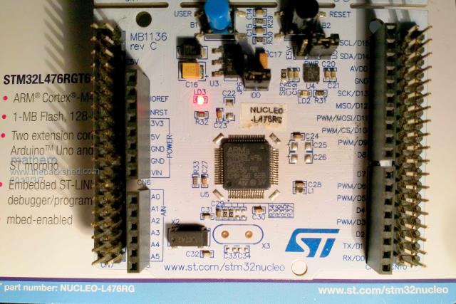 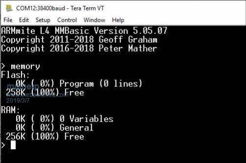 2019-03-07_031232_ArmmiteL476.zip If you have an unmodified Nucleo-L476 please could you give the above firmware a quick checkout - particularly the various special function pins (analogue, i2c, spi, etc.) Thanks |
||||
| panky Guru Joined: 02/10/2012 Location: AustraliaPosts: 1120 |
As luck would have it, there is a 476 on its way to me now ~ will try to get testing monday. Thanks for the update, panky. ... almost all of the Maximites, the MicromMites, the MM Extremes, the ArmMites, the PicoMite and loving it! |
||||
| panky Guru Joined: 02/10/2012 Location: AustraliaPosts: 1120 |
@matherp Do I take it from your picture, you have just lifted the 476 and replaced it with a 496 on the nucleo~l476rg board? panky ... almost all of the Maximites, the MicromMites, the MM Extremes, the ArmMites, the PicoMite and loving it! |
||||
| matherp Guru Joined: 11/12/2012 Location: United KingdomPosts: 11166 |
Yes - hot air gun carefully applied until the existing solder softens (unleaded unfortunately so quite hot). Remove existing chip, clean pads with solder wick, then solder the new STM32L496RGT6 chip in place. |
||||
| panky Guru Joined: 02/10/2012 Location: AustraliaPosts: 1120 |
Peter, Re the analogue inputs on the NUCLEO-L476RG - loaded with your 2019-03-07_031232_ArmmiteL476 software - all are looking good. Pins A0-A5 all appear to work correctly and respond to the A reference or the pin number correctly. Pins 10(PC2),11((PC3),22(PA6),23(PA7),24(PC4),25(PC5) and 27(PB1) all appear to work correctly. Pin 21(PA5) loads the input down when the input voltage rises above about 1.6V - I guess as it is connected via a solder bridge to LED2. Below 1.6V it appears to works correctly as an analogue input. Didn't take the bridge off as below the cutoff voltage, it looks OK. All analog voltages read about 40mV low (according to my multimeter which is a reasonable quality unit but no guarantee of its accuracy). Hope this assists. Doug. ... almost all of the Maximites, the MicromMites, the MM Extremes, the ArmMites, the PicoMite and loving it! |
||||
| matherp Guru Joined: 11/12/2012 Location: United KingdomPosts: 11166 |
Thanks for the testing Try "OPTION VCC pin(VDDA)" and see if that improves things (or makes them worse  ) ) |
||||
| panky Guru Joined: 02/10/2012 Location: AustraliaPosts: 1120 |
Excellent - analogue voltage readings now within a millivolt or 2 of the multimeter! Thanks. ... almost all of the Maximites, the MicromMites, the MM Extremes, the ArmMites, the PicoMite and loving it! |
||||
| The Back Shed's forum code is written, and hosted, in Australia. | © JAQ Software 2026 |
