
|
|
Forum Index : Microcontroller and PC projects : CMM2 case kit....(or panels)
| Author | Message | ||||
Grogster Admin Group Joined: 31/12/2012 Location: New ZealandPosts: 9935 |
I will be offering both a full case-and-panels kit, and also just the panels for those who might already have the case. 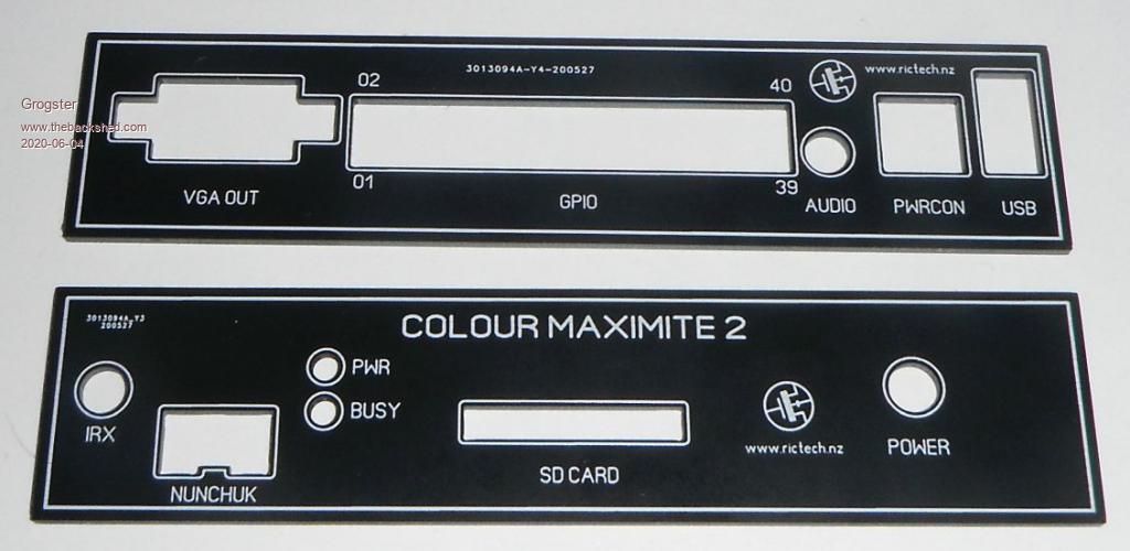 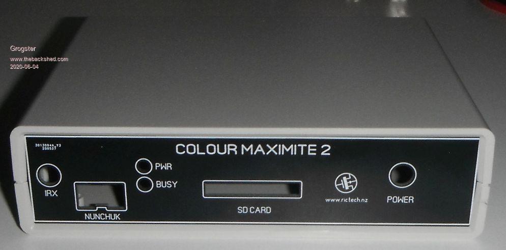 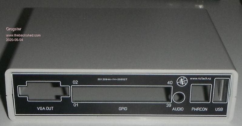 The panels were designed by Peter(matherp), but slightly 'Abused' as he said we could when he posted them in another thread.  Smoke makes things work. When the smoke gets out, it stops! |
||||
| matherp Guru Joined: 11/12/2012 Location: United KingdomPosts: 11214 |
  |
||||
| CaptainBoing Guru Joined: 07/09/2016 Location: United KingdomPosts: 2171 |
very clean looking panel Grogs, nice. Is this laser cut, pcb, 3d printed? My panels tend to be a lump of sheet ally with the holes cut (I absolutely hate chain-drilling and filing the rectangles) then I glue on a printed paper overlay with the legend ... while acceptable to me for my home-grown test kit, they don't have the same "polish" as those above, and there is always some wrinkle with alignment, no matter how careful I am. Very good. Edited 2020-06-04 21:59 by CaptainBoing |
||||
| Turbo46 Guru Joined: 24/12/2017 Location: AustraliaPosts: 1685 |
Very nice. Do you have them now and could I add one to my order? Bill Keep safe. Live long and prosper. |
||||
| Grogster Admin Group Joined: 31/12/2012 Location: New ZealandPosts: 9935 |
Hi everyone.  @ matherp: thank you.  @ CaptainBoing: No, they are made as PCB's from a PCB factory, they simply don't have any copper on either side. Just black soldermask top and bottom, and silkscreen on one side only, along with the cutouts on the outline layer. Simple and easy. @ Turbo46: Yes, and yes. They are not up on the website yet though. Do you just want the panels, or the panels AND the box? THERE IS ONE SMALL ERROR with these, and that is that I have accidentally swapped over the POWER and BUSY LED legends, which will require that you fit the LED's to the panel and secure with some glue, and then run three short wires to the board. I will fix this in the next batch of panels, and matherp has also emailed me about how to get rid of the production number that the PCB factory put on these panels. It was an option that I missed when I ordered these ones.  Panels are just panels, but the panels+box will also include the 4x 5mm spacers you need to put under the PCB to lift it up inside the box to the correct height. I don't have any 5mm spacers at the moment, but they are on order. I have 2mm, 3mm, 4mm and 6mm - but no 5mm!!!!! Go-figure.....  Smoke makes things work. When the smoke gets out, it stops! |
||||
| GregZone Senior Member Joined: 22/05/2020 Location: New ZealandPosts: 114 |
Nice work @Grogster! Just some hopefully constructive (but OCD based) thoughts� :) a. Perhaps just �IR� is more standard for the InfraRed window, instead of �IRX� b. The abbreviated �PWR� and non-abbreviated �BUSY� seems to trigger my OCD. LOL One thought would be to just remove the PWR label altogether (as this LED function is quite obvious), which would then allow the �BUSY� label to be position below the LED, consistent with the other panel labelling positions. c. Understand the Rictech logo and web address presence, however it is little overwhelming being so prominent on the front panel. Would it be acceptable / more appropriate to just feature this on the back panel? After all, the panels come in pairs. :) d. The power connector may be nicer if it was just labelled �POWER�, instead of �PWRCON�. This removes the abbreviated label conflict, and I also note we don�t have �GPIOCON�, �USBCON� etc. given the connector aspect is kinda self evident. :) e. Is anyone going to be producing a panel with the really nice full colour Colour Maximite logo? I know you can�t get multi-colour silkscreen PCBs (correct me if I�m wrong), so I guess this would be a more expensive proposition? Please don�t take any of the above as being in any way critical. It�s is just based on my initial reactions, which I freely admit are biased by my (apparent) OCD tendencies. :) Hopefully you will view constructively, as intended. |
||||
| daz6809 Newbie Joined: 23/05/2020 Location: AustraliaPosts: 1 |
@ Grogster How do I go about ordering a case? Panels and sides, happy to wait for the new batch... Cheers, Daz. |
||||
| KeepIS Guru Joined: 13/10/2014 Location: AustraliaPosts: 2107 |
"PWRCON" may be short for Power / Console. Mike NANO:Inverter V 8.2ks - Linux AvrDude GUI script V4.1 |
||||
| GregZone Senior Member Joined: 22/05/2020 Location: New ZealandPosts: 114 |
Good observation! I suspect that might be it. Thanks. |
||||
bigmik Guru Joined: 20/06/2011 Location: AustraliaPosts: 2980 |
They look pretty decent Grogster, That will save a bit of fiddling about. Hi Greg, I have produced some that were based on Geoff's artwork in the construction kit. I found I had to edit things a bit as there were some anomolies in the ones in the construction kit. ie GPIO header 1.5mm too wide on LHS, SD and POWER switch 2mm to the left Power switch 2mm too low. (mind you I had my own switch so this could be a different brand than the one quoted) nunchuck was too low Now I have the version 1.5 all in one (arrived yesterday from WhiteWizard) so there could be minor differences to the waveshare module version.. I created some templates for the cutouts and also some front panels. I printed these on photo paper. These look beautiful and glossy. I laminated them in a laminator and trimmed them to size. The idea is use thin double sided tape and stick the template to the smooth side of the plastic panel and use it to cut out the holes, Peel the template off and then carefully align the front panel to the plastic panel and its done.. A wordof warning the panel then is a bit thick to fit in the slot so I intend to bevel the inside edges of the plastic panels to make them thin enough to fit in. Here are the artworks I have edited. 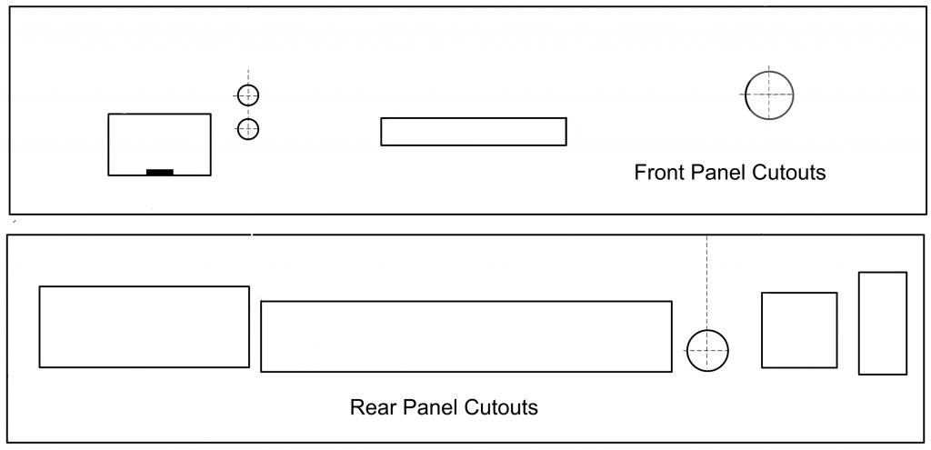 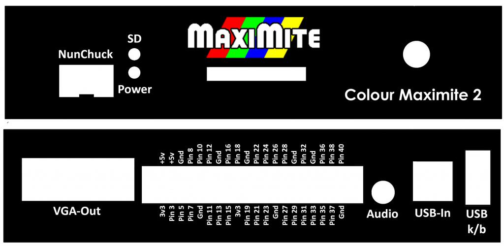 Here they are zipped up in case they lose their size/resolution Artwork.zip The idea is print one and compare to size, They should be 134mm x 30mm size, if the printed size is incorrect then use a picture editor to adjust and print again. Kind Regards Mick Mick's uMite Stuff can be found >>> HERE (Kindly hosted by Dontronics) <<< |
||||
| MauroXavier Guru Joined: 06/03/2016 Location: BrazilPosts: 307 |
As I have only a 1.4 board version, this is exactly the position of my connectors. This remembers me that I must swap them in the image on my future demo software... |
||||
| GregZone Senior Member Joined: 22/05/2020 Location: New ZealandPosts: 114 |
Hi Mick. Awesome work, they look great with the colour logo in the middle! :) Note the Nintendo NunChuk official spelling does not have the "c" before the "k". With this making the original panels a bit thick, this might be the perfect solution to team up with the 3D printed panels. ie. You could print them a layer or so thinner (do we have the original 3D files to edit?), then we would effectively have pre-cut panels of the correct thickness for the laminated photo paper print. I believe I have some glossy photo paper, and I have a 3D printer, so I'll have to give this a go. :) Thanks, Greg |
||||
| GregZone Senior Member Joined: 22/05/2020 Location: New ZealandPosts: 114 |
Hi Mick, Would you be happy to share the originals (PNG's?), as there are some artifacts, especially around the USB k/b, presumably from the lossy JPG export. Would also allow me to fix NunChuk before printing. I also thought that if the cut-outs are the exact size, then it might be beneficial to bring the black down a bit further into the cut-outs to avoid white edging (if trying to cut-out exactly on the black/white border)? Perhaps something that could be shared via github to allow contributions? Over to you. Cheers Greg ps. My waveshare based board from Gizmo has now landed in the country, so hopefully I'll actually have a CMM2 board to play with soon. |
||||
| bigmik Guru Joined: 20/06/2011 Location: AustraliaPosts: 2980 |
Hi Greg, All, Apologies to Grogster as I feel I am hijacking his thread.. Here they are in PNG format Artwork PNG.zip I fixed NunChuk before saving, incidentally I had them saved in photo-shop format so I could save in any format I like.. I am not guaranteeing that they are accurate although as far as I can tell they look fine with my All-in-One PCB.. The one exception is the NunChuk as I don't own one to try it. I worked off the originals of Geoff's in the construction pack.. I am happy for you to do whatever you like with them, I was really just showing one method of getting a Very nice front/rear panel with minimal cost.. As to the extra thickness that the tape+label make you probably could stick to an old PCB and cut it to suit instead of the plastic panels that come with the enclosure. I found that the size when printed on plain paper was different to the size when printed on photo paper (still using photo-shop to print), only slightly, but I just adjusted the ratio to suit and ended up with exact size for my printer on photo-paper. If anyone needs a set and cant resize just PM me and tell me the exact measurement of your print and I am happy to resize to suit your printer for you. Kind Regards Mick Mick's uMite Stuff can be found >>> HERE (Kindly hosted by Dontronics) <<< |
||||
| GregZone Senior Member Joined: 22/05/2020 Location: New ZealandPosts: 114 |
As a new member, I'm unsure of the correct etiquette here. In replying I was assuming this as more of a single topic for all CMM2 Case related discussion? But if this is an incorrect assumption, I guess an Admin would need to move posts related to your Case panel artwork to a new topic? Thanks Mick. I've done a quick test print on a sheet of glossy photo quality paper and the panels look really awesome! However, at the moment they don't quite line up with the 3D printed STL's in the construction pack, and the PNG print-out is coming out about 4mm narrower and 1mm lower than the JayCar case original ABS panels. Also, the 3D printed panels themselves are slightly too thick to fit in the case channels (even without allowing for the laminated printout). I have an AnyCubic i3 Mega printer. So for the moment, I'm going to need to park this until my CMM2 actually arrives (hopefully just a few days away). Then I'll be able to figure out what I need to tweak, and perhaps need to also create a fresh new Fusion 360 3D print design, so that I can adjust the sizing. Thanks again for your awesome work and sharing the PNG's! |
||||
| bigmik Guru Joined: 20/06/2011 Location: AustraliaPosts: 2980 |
Hi Greg, All, As to etiquette, I dont think I have jumped too hard on Grogster's post, as you said it is allied as far as they are both front panels.. What I meant is Grogster posted with an intent to move his really neat panels and I, almost immediately added with my 2 pennies worth. They look even better when plasticised. As I said in my first post they need to be adjusted, after a test print, to suit your particular printer. And also I have sized to suit `what I think' they should be to suit the version of CMM2 I have.. I may have stuffed up of course... Print the templates out and cut the holes and use it as a `temporary' panel when your board is screwed into the case and judge it for your self. My initial (basically Geoff's originals) were almost perfect for height/width when printed on plain paper but I was surprised that when printed on photo paper the size was a few mm out.. �Easy to adjust.. if you want me to resize to suit your printer let me know and I will do that for you, just give me the exact size of the height and width. � My printer is a Canon TS8160 Kind Regards Mick Edited 2020-06-06 16:26 by bigmik Mick's uMite Stuff can be found >>> HERE (Kindly hosted by Dontronics) <<< |
||||
| Grogster Admin Group Joined: 31/12/2012 Location: New ZealandPosts: 9935 |
Hello all. Wow - lots of replies..... @ GregZone: IRX vs.... - fair comment. But it is IRX, as in InfraRed Receiver. I hear you, though. PWR vs BUSY..... - also fair comment. But it is what it is. You can create your own ones using matherp's original gerbers.RICTECH logo.... - No. This is MY version, so my logo needs to be REASONABLY prominent, as a way to advertise my website. See above.  PWRCON..... - Does indeed mean POWER/CONSOLE as mentioned by others. MULTI-COLOUR PANEL..... - Not by me, cos most PCB houses don't support that, but it is certainly fair comment. Not offended at all. Constructive criticism makes you aware of things you perhaps did wrong. @ daz6809: Welcome to the forums. Yes, you can, but I have yet to update my website - keep an eye out for the case+panels+spacers in my PRODUCTS section. @ MauroXavier: I have 25-sets like that! I have ordered new versions that have the legend the correct way around though. @ Mik: (hijacking thread) - No, you didn't. My version is my version, but I am happy for others to post THEIR versions. Not a problem, buddy.Smoke makes things work. When the smoke gets out, it stops! |
||||
| GregZone Senior Member Joined: 22/05/2020 Location: New ZealandPosts: 114 |
@Grogster Thanks for taking time to comment on each of my points. FWIW, I'm totally onboard with every one of your replies. |
||||
| The Back Shed's forum code is written, and hosted, in Australia. | © JAQ Software 2026 |
