
|
|
Forum Index : Microcontroller and PC projects : Pickit3 and MM+ Update
| Author | Message | ||||
| AussieWombat Newbie Joined: 04/05/2018 Location: AustraliaPosts: 21 |
Hi All, I have managed to get the MPLABS X IPE to communicate to my Pickit3. But I still can't get the MM+ to connect. 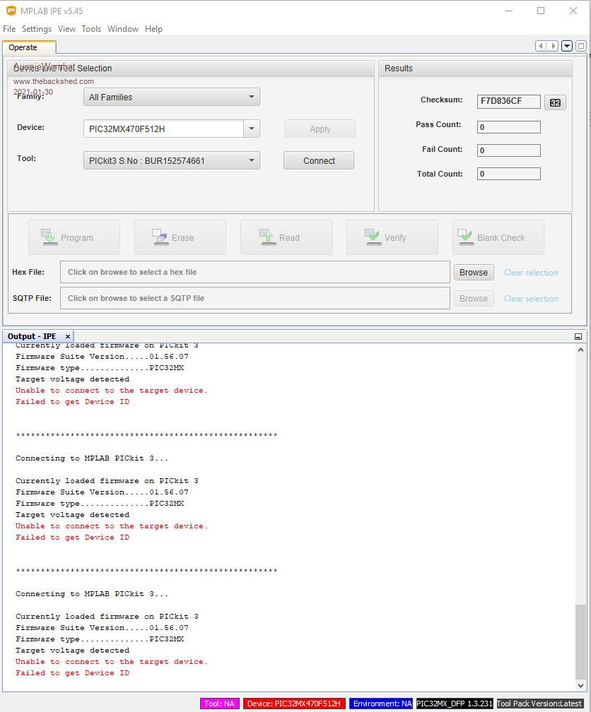 According to Gizmos page I should connect PGD to uM16 and PCC to uM15. But on my board the silkscreen print identifies uM16 as Tx3 and uM15 as Tx1 On Circuitgizmos page both uM15 and uM16 are listed as Com3 Tx 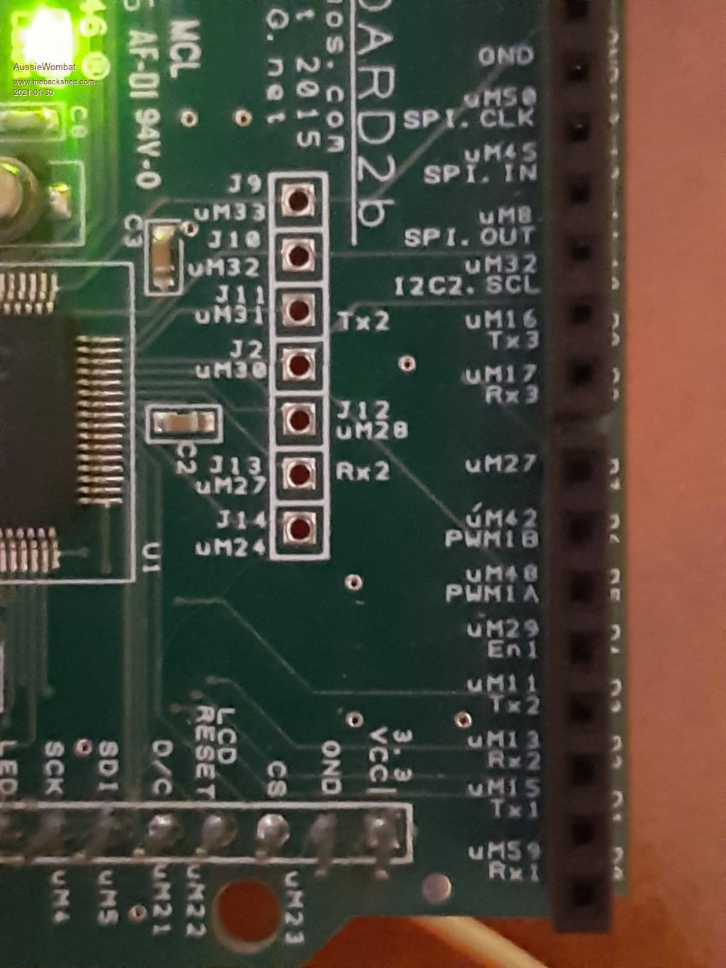 CONFUSED. Regards Aussiewombat Edited 2021-01-30 14:30 by AussieWombat |
||||
| AussieWombat Newbie Joined: 04/05/2018 Location: AustraliaPosts: 21 |
Hi all, Well I finally got the device to talk to the pickit3, and updated to latest update. seems the Dupont wires I was using must have been slightly loose. Put a slight bend in them to make a snug fit and voila. Who knew. Sorry for being a nuisance. Aussiewombat |
||||
disco4now Guru Joined: 18/12/2014 Location: AustraliaPosts: 1109 |
On the 64 pin chip there are two set of PCG/PGD pins. PCG 15 or 17 PGD 16 or 18 You can use either set. The pins can have other functions, as long as they don't have external stuff connected to them when you are trying to program it. e.g remove LCD if it uses the pins. uM16 as Tx3 and uM15 as Tx1 is correct but not really relevant to the issue unless something is connected to them. The chip need to have power on it, don't rely on the pickit3 supplying it. I have found sometimes you just need to unplug and re plug the USB on your computer and/or close and reopen MPLABS X IPE to get it to work. Even try a different USB port. I have always managed to get it to work, but sometimes it takes a bit of fiddling. Regards Gerry F4 H7FotSF4xGT |
||||
| Turbo46 Guru Joined: 24/12/2017 Location: AustraliaPosts: 1691 |
That appears correct if you look at Geoff's micromite plus manual and compare the circuit diagram with the pinout diagram. Bill Keep safe. Live long and prosper. |
||||
Grogster Admin Group Joined: 31/12/2012 Location: New ZealandPosts: 9936 |
I've not had a lot of luck with IPE and the PK3. I often got the error about bad voltage levels. I've had 100% success, with the 1455 chip and USB and the free programming utility. I now include the 1455 chip on ALL my designs, and I have not had any issues programming since then - at all. Ever. Use a 1455 based programmer debugger unit, and you will never need the gigantic Microchip download just to get the IPE either, you just need a standard USB-B cable and the free programming utility.  A little drunk/tipsy tonight, so forgive me if I get anything wrong.  Smoke makes things work. When the smoke gets out, it stops! |
||||
| The Back Shed's forum code is written, and hosted, in Australia. | © JAQ Software 2026 |
