
|
|
Forum Index : Microcontroller and PC projects : Temperate sensing: long wire & noisy EMI environment.
| Author | Message | ||||
| MustardMan Senior Member Joined: 30/08/2019 Location: AustraliaPosts: 175 |
Hello fellow hackers, I would like to read a temperature sensor at a distance of about 20 meters with the Micromite (Explore 100) in a terrible EMI environment. I thought immediately of the DS18B20... a digital signal would not suffer (too badly) from the EMI. However, ten meters is likely going to be too far for that particular device. A PTC thermistor will work easy over that distance, but the EMI would kill the accuracy of anything coming out of it. The EMI is coming from a sine-wave inverter, usually running at several tens of amps (DC side), often more. The controller is located in close proximity to the DC power cables (like 10 to 20 cm). Can't move it. The micromite communicates with a charge controller over RS232 through a digital isolator, and even so I still get occasional checksum errors in the data stream. A 'scope on the signals is not a happy sight. I can't even get it to trigger properly as the noise spikes pass the threshold (in both directions). I have to severely bandlimit the 'scope to show me anything useful. I looked for RS485 temperature senders, but am not willing to spend $50 (or more) on a module. $5 for a DS18B20 is more to my liking! Any one know of a device (like the DS18B20) that does temperature to digital in a robust, single-blob-of-plastic, low cost device? Cheers, PS: I could low-pass filter the S out of a thermistor I suppose... the temperature won't be changing that fast... |
||||
| phil99 Guru Joined: 11/02/2018 Location: AustraliaPosts: 3163 |
At the sensing end NTC thermistor connected to a dual op-amp to produce a low impedance differential signal. Use shielded 4 core cable. Differential receiver circuits have been published in Silicon Chip. Then 1Hz low pass filter before micro might do the trick. |
||||
goc30 Guru Joined: 12/04/2017 Location: FrancePosts: 435 |
a classic solution for remote temperature measurements is to use a PT100 probe with a stabilized (and precise) current generator see wiki |
||||
| Solar Mike Guru Joined: 08/02/2015 Location: New ZealandPosts: 1203 |
I use these a lot MCP9701 , they are a linear buffered active thermistor, with a very low output impedance, this will help with EMI. 20m should work ok, CPU side use a simple filter with 15K resistor and 1uf ceramic cap to gnd for noise filtering. Main reason I use them is the cpu doesn't have to change freq (on Picaxe's) or otherwise block running code to measure them, as would occur if the DS18B20 1-wire devices were used. Cheers Mike |
||||
Quazee137 Guru Joined: 07/08/2016 Location: United StatesPosts: 603 |
try the PT100 to 4-20Ma. change the 250Ohm to match the ADC max. 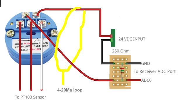 I have seen a few job sites where they used 12VDC. Not sure if they made any other changes. 4-20Ma is Great in noise environments. Edited 2021-04-23 18:47 by Quazee137 |
||||
mikeb Senior Member Joined: 10/04/2016 Location: AustraliaPosts: 177 |
Try passing the sensor wires through a small toroid ring, with enough turns to fill the core, at the micro end. I've done this in many industrial environments with excellent results. In some cases it has completely eliminated the high frequency noise from inverters. In other cases it has cleaned a data signal well enough for the UART to do its job. Worth a shot before going on to more elaborate methods. There are 10 kinds of people in the world. Those that understand binary and those that don't. |
||||
| MustardMan Senior Member Joined: 30/08/2019 Location: AustraliaPosts: 175 |
Yes, I've had problems with code blocking when reading the DS18B20... I do like the look of the MCP9700A (2deg is accurate enough for me), and I like the price! 50c a piece! The suggestion of a toroid is a good one. I did that for a system operating close to an FM transmitter years ago, which fixed a nasty RFI problem, and forgot all about it. It will likely improve the RS232 also. Many thanks for all the other suggestions, and if the 50c MCP9700 doesn't work, the next step up is likely the op-amp buffered differential (phil99), but I do like cheap and effective - especially since I don't need high accuracy. I should really have made that clear up-front. I also found the "NTA8A01" while searching. RS485. Acceptable price (lowest I saw was ~$7), but not as good as 50c (!!), and none on ebay. Cheers! |
||||
| lizby Guru Joined: 17/05/2016 Location: United StatesPosts: 3742 |
Can't say about 20 meters, but I've successfully used the DS18B20 at over 10 meters--2 15-foot dollar store 3-wire mini-stereo cables plus another 6-foot one (PICAXE running on 5V). Can usually be overcome with TEMPR START and some cleverness with timing. PicoMite, Armmite F4, SensorKits, MMBasic Hardware, Games, etc. on FOTS |
||||
| MustardMan Senior Member Joined: 30/08/2019 Location: AustraliaPosts: 175 |
@lizby I can certainly try the 18B20 over that length... the 9700 also uses 3 wires so I could change the end device without too many problems (portable soldering iron, difficult location...) and simply change code to either TEMPR that pin or analog-in on the same pin. I had an interrupt generating a slow square wave (10Hz), but it had to be accurate. The PWM (on the micromite) will only go down to 20Hz, so an interrupt with a 'IF sig=1 THEN sig=0 ELSE sig=1' 'PIN(x)=sig' did the trick. However, any calls to TEMPR (which had to be done asynchronously about once a second) would sometimes clash with the 10Hz interrupt routine and 'hold off' the interrupt for several tens/hundreds of microseconds. The square wave would no longer be an "exact" square wave, even though it would, long term, remain at 10Hz. That in turn resulted in poor performance of the controlled device. I thought (and tried) using TEMPR START, but unfortunately it did not help. I ended up rethinking the actual specified requirements and settled on an alternate solution (always helps to have 'non exacting' specifications!). Cheers, |
||||
| lizby Guru Joined: 17/05/2016 Location: United StatesPosts: 3742 |
If you had a 10Hz interrupt, I'm not sure why issuing TEMPR START and counting 10 of the interrupts before doing TEMPR and another TEMPR START would not have worked without interfering with your 10Hz timing. I was looking at a similar situation, but expecting to read 14 DS18B20s about once a minute. PicoMite, Armmite F4, SensorKits, MMBasic Hardware, Games, etc. on FOTS |
||||
| MustardMan Senior Member Joined: 30/08/2019 Location: AustraliaPosts: 175 |
Unfortunately my 10Hz was not always 10Hz - I didn't want to get into TLDR territory, so I left out a lot of detail. Bit of a problem when talking to smart people like yourself! The "10Hz" would vary depending on what the user required, from about 1Hz to 1kHz. The code tested the user input and used the PWM output for anything above 20Hz, and enabled an interrupt when below. The extra overhead of an 40 times a second (or less) interrupt was acceptable, and the delay in the interrupt routine was consistent, giving me a stable output. The effort required to calculate the number of "slow PWM output" interrupts required before a TEMPR START got nasty, especially since reading the temperature was not an exact one second. In answer, I probably could have done it, but closer examination of the requirements saved me the effort. Cheers (and spot on being so observant!) |
||||
| lizby Guru Joined: 17/05/2016 Location: United StatesPosts: 3742 |
Ah, devil in details. PicoMite, Armmite F4, SensorKits, MMBasic Hardware, Games, etc. on FOTS |
||||
| Mixtel90 Guru Joined: 05/10/2019 Location: United KingdomPosts: 8774 |
I've just got a MCP9700A to use for heatsink temperature measurement on a lab PSU that I've started. I figured it would probably be pretty reasonable for something like that - and cheap! :) Of course, the PSU case isn't 20m long... I suspect phil99's approach using the dual op-amp might be the better approach here. I'm not sure how well *anything* using digital processing of any sort would survive so a differential amp/buffer looks sensible. A lot of electricity generation systems (also noisy) use 4-20mA signals for engine and alternator temps (and you can get 4-20mA current transformers too - you'd think that was asking for trouble!) so that's also well worth considering. Mick Zilog Inside! nascom.info for Nascom & Gemini Preliminary MMBasic docs & my PCB designs |
||||
| MustardMan Senior Member Joined: 30/08/2019 Location: AustraliaPosts: 175 |
I've used 4-20 loops before (on the Explore 100, implemented using the 'click' range of boards) and have been impressed with their performance in harsh (electrical) environments. The downside - they are expensive and require non-trivial extras to work. Not that my goal is cheap. My goal is more 'simple as I can get away with'. |
||||
| Mixtel90 Guru Joined: 05/10/2019 Location: United KingdomPosts: 8774 |
I wonder if this 4-20mA would work with the MCP? I've not attempted it. :) +------+-------+--------RES-------+----- +12 | | | | | | | |-----|+\ | zen5v cap MCP | \_____|/ | | | -|- / |\ npn | | | || / | | | | +-----------+ | | | RES1 | | | | +------+-------+------------------+-------+---> | RES2 | +---- 0v The op amp would need to be a rail-rail 5v one. RES1 would be 75R to give 20mA at 100C (I think) and RES2 would be 165R to give 3.3v out at 100C. These numbers could be twiddled, of course. Mick Zilog Inside! nascom.info for Nascom & Gemini Preliminary MMBasic docs & my PCB designs |
||||
| The Back Shed's forum code is written, and hosted, in Australia. | © JAQ Software 2026 |
