
|
|
Forum Index : Microcontroller and PC projects : ST7789 SPI display without CS?
| Author | Message | ||||
bigmik Guru Joined: 20/06/2011 Location: AustraliaPosts: 2980 |
Hi Mick, It should be fairly easy to do the mod by cutting the ribbon with a sharp scalpel and straight edge as shown below. 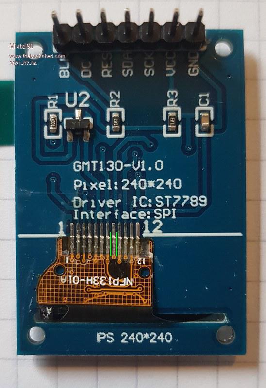 then heat Pin 8 where it joins the PCB to lift the new strip up, put a strip of insulation (tape?) under the pin 8 flap so it wont reconnect with GND and run a wire as suggested to the BLK pin (assume this is BLANK?) and remove the relevant resistor. If you wish to use the BLK feature then run CS directly to pin 8 on the ribbon (the new sliver) and secure with something to stop it tearing (nail polish), I know all techs wear nail polish, i have seen it in their kits and I have several colours myself. Regards, Mick Mick's uMite Stuff can be found >>> HERE (Kindly hosted by Dontronics) <<< |
||||
Chopperp Guru Joined: 03/01/2018 Location: AustraliaPosts: 1124 |
I went & bought a bottle of bright red & bright green the other day. On special at the Chemist (Drug store). I had run out.... Edited 2021-07-05 11:51 by Chopperp ChopperP |
||||
| Mixtel90 Guru Joined: 05/10/2019 Location: United KingdomPosts: 8778 |
Mick, thanks! You're a star! All is well now. :) That method of separating connection 8 of the ribbon works well. :) It wasn't an easy mod for me - not the sort of thing I'd want to do much of. Squinting through the small "extra strength" area of the magnifier while holding the little pcb in position and wielding a scalpel wasn't fun. lol I cut the track rather than remove R2. That will allow me to solder a bit of flexible wire onto R2 to give BLK operation if I decide to use it. It also means that I won't be straining the ribbon cable any further. No nail polish was harmed in the making of this modification. Edit: Contrast on this display isn't all that good so I've experimented with driving BLK with a PWM signal, which works well. Contrast still isn't good, but at least the backlight is controllable. :) A neutral filter of some sort helps - 2 layers of anti-static bag is a definite improvement. Edited 2021-07-08 07:19 by Mixtel90 Mick Zilog Inside! nascom.info for Nascom & Gemini Preliminary MMBasic docs & my PCB designs |
||||
| The Back Shed's forum code is written, and hosted, in Australia. | © JAQ Software 2026 |
