
|
|
Forum Index : Microcontroller and PC projects : Pico VGA - with Waveshare Dual/Quad expander
| Author | Message | ||||
| IanT Senior Member Joined: 29/11/2016 Location: United KingdomPosts: 125 |
I've been playing with the new MMB versions (both Pico & MMB4W) but I'm afraid (as usual) I'm probably lagging far behind eveyone else here. I'm only slowly exploring programmes like "gui-test" to understand how bits can be incorporated into my own applications. It's very helpful to have a working 'start' point and to experiement from there, otherwise it can all be a bit daunting. On the Pico side, I've purchased some Waveshare parts, including a Quad backplane expander. As I have an old VGA monior, I was wondering about hooking this up to the Pico via the Quad expander? In other words, instead of a dedicated Pico-VGA PCB, is it possible to route the required signals out to a (simple?) plug-in board on the Quad - giving me a VGA display on the Quad which would be better (easier for me to read) than using a small OLED (etc) display. It may be of course, that so many pins are used that other plug-ins wouldn't be viable. I've not gone though the options available (checking pins required etc) for each one but I know there are some conflicts. If viable, I could probably wire-wrap the neccessary parts on a proto-board (as I don't have any PCB skills to design one) but I don't know if this would work? (obviously pin utilisation but also signal interference etc). So if the hardare gurus could advise, at least in theory, I'd be obliged. I might also add that in the past, whilst I've often hand-wired my boards using pre-built 'modules' (opto-isolators, H-bridges etc) the commercial Pico "plug-ins" for servos, DC motor, AC relay control (and other comms options of course) not only look very quick & convenient in use but also affordable. I doubt I could make them cheaper from discete parts quite apart from how clunky some of my DIY boards look. So I do see these Pico 'accessories' as a major advantage of the PicoMite (over my PIC170 Mites). Any thoughts would be very much appreciated. Regards, IanT Edited 2022-03-09 22:19 by IanT |
||||
| Mixtel90 Guru Joined: 05/10/2019 Location: United KingdomPosts: 8682 |
You should be able to put the components for a PicoMite VGA onto a suitable board to fit your backplane (although the VGA and PS/2 connectors might need some imagination). There are only a few resistors in addition to that. Note that you have to run the VGA version of the PicoMite firmware in order to use VGA. The normal version won't work. The pins on the PicoMite VGA for the PS/2 keyboard and VGA output are fixed - you can't change them. If there are conflicts with something else then that something else has to change. PS/2 CLK - 11 PS/2 DAT - 12 VGA HSYNC - 21 VGA VSYNC - 22 VGA bit0 - 24 VGA bit1 - 25 VGA bit2 - 26 VGA bit3 - 27 If I were you I think I'd look for breakout boards for PS/2 and VGA then try to arrange them along the low-numbers side of a piece of padboard the same size as a PicoMite, leaving a gap for pins 11 & 12. Then you can put headers on both sides of it so that it plugs in on the right-hand side of the PicoMite so the sockets are accessible. Actually, this sounds like a nice little project for a PCB design. I might see if it's feasible. Edited 2022-03-09 22:47 by Mixtel90 Mick Zilog Inside! nascom.info for Nascom & Gemini Preliminary MMBasic docs & my PCB designs |
||||
| IanT Senior Member Joined: 29/11/2016 Location: United KingdomPosts: 125 |
Thank you Mick - that sounds workable. I've got a few other things to take care of at the moment but this is something that would be useful to me and perhaps others too. If you could produce a PCB 'design' (and suggest a good source for the boards - a Chinese manufacturer I assume) then I'd be happy to get some made and make them available to anyone here who might be interested in them. Regards, IanT |
||||
| Mixtel90 Guru Joined: 05/10/2019 Location: United KingdomPosts: 8682 |
This should plug into the RH end of the backplane. It accepts a 5V PS/2 keyboard and does the necessary level shifting. Note that the sockets overhang so it has to be the end of the board. The VGA socket is the compact version, which I've not found in the UK but they are easy enough to get from Chinese suppliers. 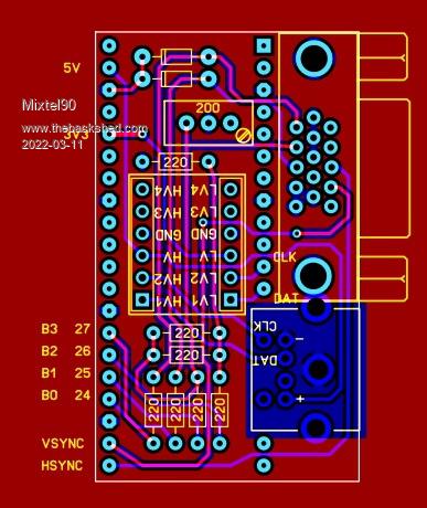 I could just do to check it over, but I think it's ok. You can get 3 of these out of a 100x100 board if they panelize them or 4 if you cut the board yourself. This is the special offer size at JLCPCB so you get 5 boards very cheaply. For those who are comparing it with the PicoMite pin layout, this backplane mirrors the PicoMite connections so left & right are reversed. EDIT: I think it's ok. :) PS2-vga adapter-gerbers.zip Edited 2022-03-11 05:34 by Mixtel90 Mick Zilog Inside! nascom.info for Nascom & Gemini Preliminary MMBasic docs & my PCB designs |
||||
| IanT Senior Member Joined: 29/11/2016 Location: United KingdomPosts: 125 |
That looks really neat Mick. I don't know if anyone else is interested in this board but I've looked at the JLCPCB site and it does seem very reasonable. So I'd be happy (assuming interest) to order some spare boards at these prices. I'd want two, Mick of course would be welcome to some - and then I'd be very happy to supply one to anyone here who would like one (for the cost of postage). I've had great fun with my Mites and I'd be very pleased to give something back to the MMB community. Mick, if you can PM me with the gerber file and advise what type of board I need to order or - possibly a much safer approach, order some PCBs for me and I'll pay your costs in advance. Whilst I don't have any PCB design skills, I have been busy learning Solid Edge 3D CAD recently. I will therefore probably produce a 3D printed enclosure for the Quad/VGA combo. Again, I'd be happy to share the .STL with anyone who would like it. So if anyone else wants one of these boards (for the cost of postage - I'm in UK) then please let me know. Thank you again for helping with this Mick. Much appreciated. Regards, IanT |
||||
| Mixtel90 Guru Joined: 05/10/2019 Location: United KingdomPosts: 8682 |
Gerbers are in my last post. :) Ordering from JLCPCB is dead easy. Just accept all the defaults and you'll get five individual green PCBs with white screen printing. You can change the colours very easily, but it adds 2 days to your order. I've not used their panelization system so I can't help much with that, sorry. They would probably be able to fit 3 on a single 100x100 though (there has to be a margin on two opposite sides), then you can just snap them apart. If you want them to do that it'll cost a bit extra, I think. Incidentally, if someone wanted to play, it should, in theory, be possible to fit female headers on the back of this board and plug a PicoMite onto the back of it - but watch the pins behind the keyboard socket, they may have to be trimmed down. You'd have to power it from USB and there's no audio output or SDcard. It's probably not worth it. Mick Zilog Inside! nascom.info for Nascom & Gemini Preliminary MMBasic docs & my PCB designs |
||||
| IanT Senior Member Joined: 29/11/2016 Location: United KingdomPosts: 125 |
Ok Mick - sorry missed that - I'll wait to see if there is any interest and then order some. Would you like a couple? :-) Regards, IanT |
||||
| Mixtel90 Guru Joined: 05/10/2019 Location: United KingdomPosts: 8682 |
Thanks, Ian. I wouldn't mind just one if you don't mind. Mostly so I can see what to fix if/when people complain. ;) Mick Zilog Inside! nascom.info for Nascom & Gemini Preliminary MMBasic docs & my PCB designs |
||||
| Mixtel90 Guru Joined: 05/10/2019 Location: United KingdomPosts: 8682 |
Erm... I got a bit carried away and designed a little board to take the above little board, or an ordinary PicoMite with two expansion modules. It's 100mm wide. 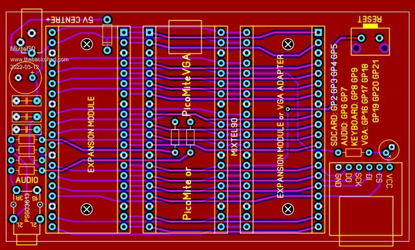 I really should stop getting these ideas... :) Edited 2022-03-12 06:12 by Mixtel90 Mick Zilog Inside! nascom.info for Nascom & Gemini Preliminary MMBasic docs & my PCB designs |
||||
| al18 Senior Member Joined: 06/07/2019 Location: United StatesPosts: 233 |
Mick, The expansion board looks good, but seems to be missing a 3.3v LDO regulator. Edited 2022-03-12 07:49 by al18 |
||||
| Mixtel90 Guru Joined: 05/10/2019 Location: United KingdomPosts: 8682 |
That's because it hasn't got one. It's using the switching reg on the PicoMite. Unless you are going to draw more than a couple of hundred mA there's no point in fitting one really - apart for wanting quiet audio, I suppose. This board is really intended to take the VGA board above and one more expansion board so it's not a lot - the VGA board draws virtually nothing. The little barrel jack feeds up to 5V into VSYS via a diode. You could plug two AA cells in series into there. When powered from USB the diode is reverse biased so they don't get damaged. The Pico will run from them when the USB supply is removed. 3V is enough - you can drop to less than 2V on VSYS. Mick Zilog Inside! nascom.info for Nascom & Gemini Preliminary MMBasic docs & my PCB designs |
||||
| The Back Shed's forum code is written, and hosted, in Australia. | © JAQ Software 2026 |
