
|
|
Forum Index : Microcontroller and PC projects : RS485 questions
| Author | Message | ||||
Grogster Admin Group Joined: 31/12/2012 Location: New ZealandPosts: 9996 |
Interesting. Thanks. I guess what I am after, is best described as "Multi-point to point" arrangement. All the NODES need to initiate transmission back to the panel when they want attention, and the panel acknowledges the node that called, and decides what to do. This sounds like the reverse of what 485 does, so I might be barking up the wrong tree thinking I can use it like that.  Thoughts? Comments? Perhaps I do indeed need a four-wire type system as mentioned by Mick. A transmit bus from the nodes to the panel that the panel listens to for calls, and a receive bus to the nodes from the panel that the panel can send acknowledge codes back to the node that called on the other bus. Just tossing ideas around at this point. RS485 simply might not be a protocol I can use in this kind of arrangement. Smoke makes things work. When the smoke gets out, it stops! |
||||
| Turbo46 Guru Joined: 24/12/2017 Location: AustraliaPosts: 1694 |
Yes, it does seem that R5485 is not what you want. 4-wire RS422 is more like it. The problem then is collision avoidance and/or handling when two or more nodes want to talk at the same time. Unless you can poll each node rapidly and they respond with a NACK or data as appropriate? If you get the NACK at least you know the node is still active and it does avoid collisions. Bill Keep safe. Live long and prosper. |
||||
| Mixtel90 Guru Joined: 05/10/2019 Location: United KingdomPosts: 8965 |
A simpler possibility is for the nodes to actually be slaves. They are periodically scanned by the master and a 2-byte message triggers an interrupt on them. They read this, the first byte is a slave address, the second is a command. If addressed, they respond with a single status byte. That contains a flag if the slave needs attention. The master will then, serially, scan each slave with the attention flag set and deal with it. After the slaves have been handled the master goes back to scanning the status flags again. Or something along those lines anyway. It probably takes more time to explain than to do. RS485 can be pretty fast. :) Mick Zilog Inside! nascom.info for Nascom & Gemini Preliminary MMBasic docs & my PCB designs |
||||
| Grogster Admin Group Joined: 31/12/2012 Location: New ZealandPosts: 9996 |
That sounds like something I could play with.  Is RS485 hot-swappable, or do they all need to stay connected all the time? Ignore polling all the nodes(that would fail if one node was unplugged) for the moment. Smoke makes things work. When the smoke gets out, it stops! |
||||
| Turbo46 Guru Joined: 24/12/2017 Location: AustraliaPosts: 1694 |
Multiple RS485 slaves are usually daisy chained. Looped from one to the other to the next with a terminating resistor at each end. Not passed through and forwarded on so if one fails the rest should still work (unless it goes short circuit). If you use a connector like the one below to loop in and out of you can unplug one without affecting the others (timeouts and retries aside). 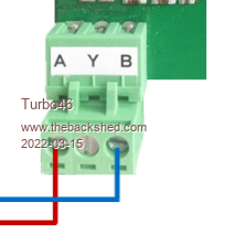 Bill Keep safe. Live long and prosper. |
||||
| Grogster Admin Group Joined: 31/12/2012 Location: New ZealandPosts: 9996 |
Ta. I use pretty much those same kind of plug-and-socket PCB terminals, and that was what I was planning to use, so that sounds good. Once my 485 modules arrive, I can hook up a chain of them and then do some experimenting. Smoke makes things work. When the smoke gets out, it stops! |
||||
| Tinine Guru Joined: 30/03/2016 Location: United KingdomPosts: 1646 |
@bigmik Hey Mick, Good to learn about the real-world experience. I omitted the ground, albeit accidentally on a somewhat long-ish, 230 KBaud run and all was fine. Having said that, lots of vendors still insist on providing the ground. OTOH, we opto-isolate our digital inputs, specifically so that we avoid having a common ground with external equipment  Regards, Craig |
||||
| Volhout Guru Joined: 05/03/2018 Location: NetherlandsPosts: 5994 |
Hi Craig, Providing ground is not essential to the operation of the RS485 bus. #1: the provided ground by the bus is always "weaker" than the earth/ground connection in the installation #2 the signals are differential within the operating window of the receivers and transmitters. And since receivers are self biased, even opto isolated RS485 can do without ground, although you often see ground connected in such isolated installations. What is sometimes applied is a shield. Even for differential systems. Shielding is typically hard wired at the controller chassis, and capacitive connected to each "slave". Sometimes slaves have a dedicated "capacitive coupled" shield pin. If you are in a dirty environment is may be beneficial to use optical isolated RS485. This allows common mode voltage changes to exceed 1V (1V is about the max a RS485 receiver can absorb, depending on the receiver silicon. 3.3V powered chips are typically more sensitive to common mode disturbances, than their 5V siblings. But this is no "law"). You often see isolated RS485 in large industrial installations. Where equipment is sometimes hundreds of meters apart (i.e. a chemical plant). Not in the typical inside installation (your domain), where grounding can be firm by a big copper bar or metal frame. PicomiteVGA PETSCII ROBOTS |
||||
| Tinine Guru Joined: 30/03/2016 Location: United KingdomPosts: 1646 |
@Turbo46 @Grogster  That's what I call a proper connector. No to Molex and no to D-connectors. Screws are a bit 20th century though. I prefer the screwless type and bootlace ferrules on the wires Craig |
||||
| Volhout Guru Joined: 05/03/2018 Location: NetherlandsPosts: 5994 |
RS485 is typically used in installations, and is not per-say hot swappable. The bus can have multiple devices on it, but general way of installing is that there is a termination of 100-120 ohm at both ends of the bus. In many cases this is at the controller, and the most remote slave. Slaves in between (these must have the termination disabled) could be removed or added...but.... The controller software must be able to cope with this. The protocol is a dialog where the master asks the slave for response, or orders it to perform tasks. Timeouts can be added, but while waiting for the slave to respond the bus is typically idle. So removing a slave can slow down the system significantly. Adding slaves, the master must scan the bus (including timeouts when there is not reponse) for new devices. Hotplugging is technically possible for all but the outermost RS485 devices that terminate the bus (or you have to add separate termination, and disable all terminations on devices) PicomiteVGA PETSCII ROBOTS |
||||
| Volhout Guru Joined: 05/03/2018 Location: NetherlandsPosts: 5994 |
Common mode is minimal 10V (not 1V), in many cases -7V to +12V or even more. PicomiteVGA PETSCII ROBOTS |
||||
| Tinine Guru Joined: 30/03/2016 Location: United KingdomPosts: 1646 |
@Volhout Even the issue of shielding seems to be controversial. I think it boils down to good engineering practices and this is one of the areas where I pull the scope out to see what I'm dealing with. In my NMC case, I absolutely need a ground if I am using "dynamic addressing" because this requires an extra addressing wire, daisy-chained from device to device. Craig |
||||
| Tinine Guru Joined: 30/03/2016 Location: United KingdomPosts: 1646 |
Serial Port Complete Highly recommended. Edited 2022-03-16 01:10 by Tinine |
||||
| Turbo46 Guru Joined: 24/12/2017 Location: AustraliaPosts: 1694 |
If it's really dirty like connecting to devices in the switchyard of a high voltage electricity substation, fibre optics is the way to go. They now use DIN rail 'interface converters' for that. We had rules for earthing (and they still do) but sometimes rules have to be broken. But the shield should still be only terminated at one end. If you need to interconnect the earths of two devices - use a separate wire out of the shielded twisted pair that you are using for the RS485. Bill Keep safe. Live long and prosper. |
||||
bigmik Guru Joined: 20/06/2011 Location: AustraliaPosts: 2981 |
G'day Lads, I am reading this with interest. In reflection, we DID have GNDs connected BUT, the GNDs were not transferred through to the terminals. Let me explain. We used 5pair (10wires) cat 3 with shield. Each terminal had two ports (A and B) there were two servers one managing A the other B. We daisychained (NEVER STAR) the cables from location to location (could be as many as 10 locations) each location had a backbone with a 12 pin molex connectors that the feed cables to each terminal was connected to. These feed cables NEVER had the GNDs connected. The GNDs were connected to Frame GND at the servers only along with the shield (similarly ONLY) connected at the server end. The 10 wires were (pair based so + was the same pair as the relevant-), direction wrt the server Tx+ Tx- Rx+ Rx- GND GND Tx2+ Tx2- Rx2+ Rx2- We ran a maximum of 16 terminals no matter how many locations the line went to (in reflection we could had had upto 16 locations, eg when we had terminals in marquees). We put a terminator at the end of the line of the last location that held terminals. I am not sure but I think the servers had termination built in. The protocol was along these lines, (double this as the 2 servers worked independently) Server says "terminal 0 are you there? - hex 20 00 04) terminal 1 was 20 01 04 and so on. Terminal responds with "yes boss I am here" - hex 20 00 05 followed by any data it needed to transmit. If the terminal had nothing it would just acknowledge that it was awake 20 00 05 The server would poll 3 times and if no response would go to the next terminal, if after x many poll attempts the server placed the terminal in a "slow poll table" where that "drop" would only ever be polled every x (maybe 15-20 seconds or so)this allowed the communication to not be halted/delayed due to slow or non existent terminal. If the terminal suddenly woke up the server would see it in 15sec or so then place it back in the normal poll table. The terminals were hot plug-able so that answers the question to that. We used to move terminals from a quiet location to a busy one or swap out faulty terminals on a very regular basis. We raced Victoria's race meetings on this type of setup for over 30 years including the Melbourne Cup (Australia's biggest horse race) we could manage over 500 terminals at upto 1500m away. You might be shocked to know that servers were 486 based with 3x stallion 16 port cards (RS232 but they had 485 converters built in) which gave 48 channels of 16 terminals capacity although they never quit hit that max. capacity. The terminals in the early days were 6800 based but were replaced early in my tenure by 386 based terminals. I am still amazed at how fast these old beasts could pump the data through, which is on reason the company took so long to replace them. Sorry to bore you blokes to tears but I really am impressed by the reliability of RS485 (4wire) through all sorts of environmental challenges. We did have some instances when we found someone had set up industrial fridges/generators/transmitters you name they did it right over or next to our installation that caused some issues. Easy enough to fix but not to locate the source of the problem. Good luck with your setup. Regards, Mick Mick's uMite Stuff can be found >>> HERE (Kindly hosted by Dontronics) <<< |
||||
| Turbo46 Guru Joined: 24/12/2017 Location: AustraliaPosts: 1694 |
Interesting Mick, That sounds like the type of system Grogster may want to implement. How were the addresses set up? Switches or links? Some MODBUS slaves default to a particular address and baud rate and are set up by sending a new address and baud rate to internal registers which are saved in non-volatile memory for next startup. Other SCADA systems I worked with used switches or links but that requires too many DI on a little micro. Bill Keep safe. Live long and prosper. |
||||
| lizby Guru Joined: 17/05/2016 Location: United StatesPosts: 3816 |
While awaiting my RS485-to-ttl modules and an order of 8AWG solar cable, lugs, and Anderson connectors, I decided to write a display and emulator for the Renogy 20A Solar Charger. The PDF link is on this github site: Renogy MODBUS pdf I haven't done much so far with MMB4W, so thought this would be a good little test of it, with one MMBasic program emulating the Renogy device as MODBUS server, and another as MODBUS client displaying the data. Two sessions of MMB4W worked very well for this. Instead of RS485, the client wrote a file containing the MODBUS message, and the server read it and responded by writing another file with the MODBUS response. MMB4W made this very easy. I edited the two files in Notepad++, and issued a LOAD for the program and then a RUN. When a program errored out (or I terminated with <ctrl-C>), I edited and saved the code in Notepad++, and then back in the MMB4W window, pushed up arrow twice and <Enter> to reload, and up-arrow twice and <Enter> to run. Easy-peasy.  Here's a youtube video, with the simulation starting with the battery fully discharged (which I'm calling 12V). The charge level indicator on the right turns from red to green (indicating level of charge) in 8 steps. When fully charged, the sun goes down (effectively), and the battery discharges. When fully discharged, the battery indicator background goes from green to red. When the sun comes up, the battery starts recharging. Renogy Solar Charge Controller Display Simulation (Sorry for the annoying wiggle.) Here's the server (Renogy) code: ' rs485server.bas emulates Renogy 20A solar controller ' dim integer i,j,k,l,m,register,nwords,pass,crc_table(255) ' lookup table for CRC generation 'dim integer SOC=76,batVolts=133,chgCurrent=82,temp=22,panelV=331,panelC=87,chgWatts dim integer SOC=0,batVolts=120,chgCurrent=82,temp=22,panelV=331,panelC=87,chgWatts dim integer flagChargeDirection=1 dim string msg ' open "com1:9600" as #1 genCRCtable ' generate the lookup table do ' if loc(1) then ' message coming if MM.INFO(EXISTS FILE "reqMODBUS.txt") then pause 100 ' allow many characters to arrive open "reqMODBUS.txt" for input as #1 msg=input$(100,#1) ' get the message; assume read n words from register close #1 on error skip kill "reqMODBUS.txt" ' e.g.: 01 03 000A 0001 A408 ' read address 000A, one word (return # bytes) l=len(msg): for i=1 to l: print hex$(asc(mid$(msg,i,1)),2)+" ";: next i register=asc(mid$(msg,3,1))*256 + asc(mid$(msg,4,1)) print " - "+hex$(register) nwords=asc(mid$(msg,5,1)) msg="" select case register case &h0A: ' volts & amps msg=chr$(1)+chr$(3)+chr$(2)+chr$(12)+chr$(20) ' return 2 bytes--voltage, amps case &h0C: ' model msg=chr$(1)+chr$(3)+chr$(16)+" MT4830 " case else: ' msg=chr$(1)+chr$(3)+chr$(nwords*2) ' # bytes to return for i=1 to nwords select case register ' dim integer SOC=76,batVolts=133,chgCurrent=82,temp=22,panelV=144,panelC=87,chgWatts case &h0100 ' Battery capacity SOC 0 to 100: 01 03 0100 0002 C5F7 msg=msg+chr$(0)+chr$(SOC) case &h0101 ' Battery voltage * 0.1V 01 03 0101 0001 D436 msg=msg+chr$(0)+chr$(batVolts) case &h0102 ' Charging current * 0.1V (to battery) msg=msg+chr$(0)+chr$(chgCurrent) case &h0103 ' Controller temperature msg=msg+chr$(0)+chr$(temp) case &h0104 ' Street light (load) voltage msg=msg+chr$(0)+chr$(0) case &h0105 ' Street light (load) current Street light current * 0.01 A msg=msg+chr$(0)+chr$(0) case &h0106 ' Street light (load) power msg=msg+chr$(0)+chr$(0) case &h0107 ' Solar panel voltage Solar panel voltage * 0.1 V msg=msg+chr$(panelV/256)+chr$(panelV mod 256) case &h0108 ' Solar panel current * 0.1 (to controller) msg=msg+chr$(0)+chr$(panelC) case &h0109 ' Charging power Actual value W chgWatts=panelV*panelC/100 msg=msg+chr$(chgWatts/256)+chr$(chgWatts mod 256) case &h010A ' Light On/ Off command 0 or 1 case &h010B ' Battery's min. voltage of day case &h010C ' Battery's max. voltage of day case &h010D ' Max. charging current of day case &h010E ' Max. Discharging current of day case &h010F ' Max. charging power of day case &h0110 ' Max. discharging power day case &h0111 ' Charging amp-hrs of day case &h0112 ' Discharging amp-hrs of day case &h0113 ' Power generation of day kWh case &h0114 ' Power consumption of day case &h0115 ' number of operating days case &h0116 ' number of battery over-discharges case &h0117 ' number of battery full-charges end select register=register+1 next i end select if msg <> "" then msg=msg+CRC16$(msg) open "answrMODBUS.txt" for output as #1 print #1,msg close #1 l=len(msg): ?" ";: for i=1 to l: print hex$(asc(mid$(msg,i,1)),2)+" ";: next i: ?"" else endif pass=pass+1 if pass=25 then ' cycle back flagChargeDirection=1-flagChargeDirection pass=0 endif if flagChargeDirection then ' charging ' dim integer SOC=76,batVolts=133,chgCurrent=82,temp=22,panelV=144,panelC=87,chgWatts SOC=min(SOC,96)+4 batVolts=min(batVolts,144)+1 panelV=120+(rnd*25) panelC=rnd*88 chgCurrent=max(panelC,5)-5 else SOC=max(SOC,4)-4 batVolts=max(batVolts,121)-1 chgCurrent=0:panelV=0:panelC=0 endif endif loop '------------------------------------------------------------ ' from: ' http://fruitoftheshed.com/MMBasic.Modbus-CRC-uses-the-table-lookup-method-for-speed.ashx 'generates a lookup table for fast crc calculation SUB genCRCtable LOCAL i%, j%, k%, crc_const% = &HA001 FOR i% = 0 TO 255 k% = i% FOR j% = 1 TO 8 IF k% AND 1 THEN k% = k% >> 1 k% = k% XOR crc_const% ELSE k% = k% >> 1 END IF NEXT j% crc_table(i%)=k% NEXT i% END SUB ' ' returns the CRC as a string FUNCTION CRC16$(a$) LOCAL CRC% = &HFFFF, n% FOR n% = 1 TO LEN(a$) CRC% = (CRC% >> 8) XOR crc_table(CRC% XOR ASC(MID$(a$, n%, 1)) AND &HFF) NEXT n% CRC16$ = CHR$(CRC% AND &HFF) + CHR$((CRC%>>8) AND &HFF) END FUNCTION '------------------------------------------------------------- And the client (display) code: ' graphicsdemo.bas const indigo=&H4b0082 const lavender=&He6e6fa const lemonchiffon=&Hfffacd const gold=&HFFD700 dim integer i, ii,j, jj, fnt, flgClr, addr dim integer crc_table(255) ' lookup table for CRC generation dim integer sysVolts,maxCurrent dim string lastTime,pcnt,sVal,msg,msg0,msg1,msg2,msghex, msg_in dim string lbl(7)=("","State of Charge","Battery Voltage","Charging Current","Battery Temperature","Panel Voltage","Panel Current","Charging Watts") genCRCtable ' generate the MODBUS CRC lookup table msg=chr$(1)+chr$(3)+chr$(1)+chr$(0)+chr$(4) ' read 0100, 4 words addr=&h0100 '+chr$(1)+chr$(1)+chr$(1)+chr$(2) 'msg=msg+chr$(1)+chr$(3)+chr$(1)+chr$(7)+chr$(1)+chr$(8)+chr$(1)+chr$(9) msg=msg++CRC16$(msg) msg1=msg ' SOC,batVolts,chgCurrent,temp msg0=chr$(1)+chr$(3)+chr$(0)+chr$(10)+chr$(1) ' read 000A, 1 word - voltage, max current msg2=chr$(1)+chr$(3)+chr$(1)+chr$(7)+chr$(4) ' read 0007, 3 words, panelV,panelC,chgWatts fnt=3 ' mode 1 ' 800x600 ' mode 7 ' 320x240 ' mode 8 ' 640x480 mode 13: fnt=2 ' 400x300 j=mm.vres/12 ' row height for 12 rows jj=mm.hres/12 cls font fnt box 0,0,mm.hres,mm.vres,,,rgb(black) ' box around circumference text mm.hres/2,4,"Renogy Solar Charge Controller",c,fnt,,rgb(cyan) ' header text mm.hres/2, j+4, date$+" "+time$, c,2 if mm.hres=400 or mm.hres=480 then: fnt=1 font fnt rbox jj/10,2*j,mm.hres/8*1.5,j-3,,,rgb(green) text jj/4,2*j+6," MAINS",,fnt,,rgb(black),rgb(green) rbox mm.hres/8*3.25,2*j,mm.hres/8*1.5,j-3,,,rgb(green) text mm.hres/8*3.25+jj/3,2*j+6," SOLAR",,fnt,,rgb(black),rgb(green) rbox mm.hres/8*6,2*j,mm.hres/8*1.6,j-3,,,rgb(green) text mm.hres/8*6+jj/4,2*j+6," BATTERY",,fnt,,rgb(black),rgb(green) ' dim integer SOC=76,batVolts=133,chgCurrent=82,temp=22,panelV=144,panelC=87,chgWatts dim integer SOC=-4,batVolts=120,chgCurrent=82,temp=22,panelV=144,panelC=87,chgWatts chgWatts=panelV*panelC/10 on error skip kill "answrMODBUS.txt" do if time$<>lastTime then lastTime=time$ text mm.hres/2, j+4, " "+date$+" "+time$+" ", c,2,,rgb(yellow) endif ' if mid$(time$,8,1)="0" then ' every 10 seconds ' if val(mid$(time$,7,2)) mod 4 = 0 then ' every 4 seconds if val(mid$(time$,7,2)) mod 2 = 0 then ' every 2 seconds for ii=1 to 3 if ii=1 then: msg=msg1: elseif ii=2 then: msg=msg0: else: msg=msg2: endif on error skip open "reqMODBUS.txt" for output as #1 if MM.ErrNo Then goto nextLoop print #1,msg; on error skip close #1 pause 500 on error skip open "answrMODBUS.txt" for input as #1 if MM.ErrNo <> 0 Then text mm.hres/2, j*3, " No response to MODBUS request", c,7,,rgb(yellow) ' print " No response to MODBUS request" else text mm.hres/2, j*3, space$(50), c,7,,rgb(yellow) msg_in=input$(100,#1) close #1 kill "answrMODBUS.txt" if msg=msg1 then ' 4 words of values for registers &h100, &h101, &h102, &h103 l=min(50,len(msg_in)): msghex="" for i=1 to l: msghex=msghex+hex$(asc(mid$(msg_in,i,1)),2)+" ": next i ' text mm.hres/2, j*3, msghex, c,7,,rgb(red) SOC=asc(mid$(msg_in,4,1))*256+asc(mid$(msg_in,5,1)) batVolts=asc(mid$(msg_in,6,1))*256+asc(mid$(msg_in,7,1)) chgCurrent=asc(mid$(msg_in,8,1))*256+asc(mid$(msg_in,9,1)) temp=asc(mid$(msg_in,10,1))*256+asc(mid$(msg_in,11,1)) else if msg=msg0 then sysVolts=asc(mid$(msg_in,4,1)): maxCurrent=asc(mid$(msg_in,5,1)) elseif msg=msg2 then panelV=asc(mid$(msg_in,4,1))*256+asc(mid$(msg_in,5,1)) ' (*10) panelC=asc(mid$(msg_in,6,1))*256+asc(mid$(msg_in,7,1)) ' (*10) chgWatts=panelV*panelC/100 endif endif display endif next endif if mid$(time$,8,1)="6" then ' clear error (if present) text mm.hres/2, j*3,space$(50), c,7,,rgb(yellow) endif nextLoop: ' jump to here from file error loop sub display text mm.hres/8*2.6,2*j+6,str$(sysVolts)+"V",,fnt,,rgb(green),rgb(black) text mm.hres/8*5,2*j+6,str$(maxCurrent)+"A",,fnt,,rgb(green),rgb(black) for i=1 to 7 : rbox mm.hres/8+(jj/2),(i+3)*j,mm.hres/8*4,j-3,,,lemonchiffon : next i ' for i=1 to 8 : rbox jj/2,(i+3)*(j),mm.hres/8-1,j-3,,,rgb(red) : next i for i=1 to 8 if SOC > (100-(i*12.5)) then: clr=rgb(green): else: clr=rgb(red): endif box jj*10,((i+3)*j)-j/2,mm.hres/8-1,j,,,clr next i for i=1 to 7 select case i case 1: sVal=" "+str$(SOC)+"%" case 2: sVal=" "+str$(int(batVolts/10))+"."+str$(int(batVolts-int(batVolts/10)*10))+"V" case 3: sVal=" "+str$(int(chgCurrent/10))+"."+str$(int(chgCurrent-int(chgCurrent/10)*10))+"A" case 4: sVal=" "+str$(temp)+"`" case 5: sVal=" "+str$(int(panelV/10))+"."+str$(int(panelV-int(panelV/10)*10))+"V" case 6: sVal=" "+str$(int(panelC/10))+"."+str$(int(panelC-int(panelC/10)*10))+"A" case 7: sVal=" "+str$(int(chgWatts/10))+"W" if chgWatts=0 then rbox mm.hres/8*3.25,2*j,mm.hres/8*1.5,j-3,,,rgb(red) text mm.hres/8*3.25+jj/3,2*j+6," SOLAR",,fnt,,rgb(black),rgb(red) else rbox mm.hres/8*3.25,2*j,mm.hres/8*1.5,j-3,,,rgb(green) text mm.hres/8*3.25+jj/3,2*j+6," SOLAR",,fnt,,rgb(black),rgb(green) endif end select text mm.hres/8*4/2+mm.hres/8+(jj/2),(i+3)*j+6,lbl(i)+sVal,c,fnt,,rgb(black),lemonchiffon next i flgClr=0: pcnt="" ' marker for displaying state of charge for i=1 to 8 if SOC > (100-(i*12.5)) then: clr=rgb(green): flgClr=1: else: clr=rgb(red): endif if flgClr=1 then if pcnt="" then ' first time over threshold pcnt=str$(SOC)+"%" else pcnt=" " endif endif text jj*10+10,(i+3)*j-(j/4),pcnt,,fnt,,rgb(black),clr next i if batVolts<121 then ' load turned off rbox mm.hres/8*6,2*j,mm.hres/8*1.6,j-3,,,rgb(red) text mm.hres/8*6+jj/4,2*j+6," BATTERY",,fnt,,rgb(black),rgb(red) pause 3000 else rbox mm.hres/8*6,2*j,mm.hres/8*1.6,j-3,,,rgb(green) text mm.hres/8*6+jj/4,2*j+6," BATTERY",,fnt,,rgb(black),rgb(green) endif end sub '------------------------------------------------------------ ' from: ' http://fruitoftheshed.com/MMBasic.Modbus-CRC-uses-the-table-lookup-method-for-speed.ashx 'generates a lookup table for fast crc calculation SUB genCRCtable LOCAL i%, j%, k%, crc_const% = &HA001 FOR i% = 0 TO 255 k% = i% FOR j% = 1 TO 8 IF k% AND 1 THEN k% = k% >> 1 k% = k% XOR crc_const% ELSE k% = k% >> 1 END IF NEXT j% crc_table(i%)=k% NEXT i% END SUB ' ' returns the CRC as a string FUNCTION CRC16$(a$) LOCAL CRC% = &HFFFF, n% FOR n% = 1 TO LEN(a$) CRC% = (CRC% >> 8) XOR crc_table(CRC% XOR ASC(MID$(a$, n%, 1)) AND &HFF) NEXT n% CRC16$ = CHR$(CRC% AND &HFF) + CHR$((CRC%>>8) AND &HFF) END FUNCTION '------------------------------------------------------------- I picked mode 13 for the display, because at 400x300, it's closest to an ILI9488 with 480x320 on a picomite. ~ Edited 2022-03-17 10:13 by lizby PicoMite, Armmite F4, SensorKits, MMBasic Hardware, Games, etc. on FOTS |
||||
| Volhout Guru Joined: 05/03/2018 Location: NetherlandsPosts: 5994 |
Hi lizby, Nice demo. Doesn't happen very often that the instrument (the charger) is simulated. This gives me new idea's.... Why didn't you simulate using standard serial (USB-serial) ports ? As I understand all communication between PC program and simulated charger uses 2 files (req and answ) that are created/deleted for each message. Volhout PicomiteVGA PETSCII ROBOTS |
||||
| lizby Guru Joined: 17/05/2016 Location: United StatesPosts: 3816 |
It was originally my intention to use usb/serial, since that would be closer to the actual hardware to be implemented, but then I realized that by using files to do the exchange of MODBUS messages, I could do it all without having to plug anything into my laptop. Now that all has been debugged, it would be easy to switch communications to usb/serial, or even to usb/serial connected to ttl/RS485 modules. I may still try that, but I have wire lug crimping to do and connections to make on my solar setup before I get to that. I was pleased to figure out a simulation of the charge controller, which, while not realistic, at least exercised the display and the communications in a reasonable manner. ~ Edited 2022-03-17 23:21 by lizby PicoMite, Armmite F4, SensorKits, MMBasic Hardware, Games, etc. on FOTS |
||||
| The Back Shed's forum code is written, and hosted, in Australia. | © JAQ Software 2026 |
