
|
|
Forum Index : Microcontroller and PC projects : OPTION settings for Waveshare Pico displays sans MISO pins ?
| Author | Message | ||||
| Mixtel90 Guru Joined: 05/10/2019 Location: United KingdomPosts: 8815 |
1. Beep raises the GPpin for a set time then lowers it again, that's all. It doesn't produce a tone. It's relying on you using an active piezo buzzer, not the passive magnetic one that's on the board. It will never work. 2. GP14 is allocated to Touch beep in the above listing. You can't allocate it to PWM if you do that. I think Peter is currently sorting out a bug that prevents you allocating a single pin to PWM. Up until now you had to allocate both pins, even if you only needed one, so you couldn't use GP14 if GP15 was already in use. Check the latest release. You can operate the buzzer without using any sort of Beep or Play command. One way is to use the PULSE command in a loop. That outputs a single pulse on the pin. If you then use PAUSE and loop back to the PULSE command you'll get a tone whose frequency depends on the PAUSE value. PULSE toggles the pin on each use so you get a square wave. If you run the loop for a set number of times in a FOR-NEXT then you can set the length of the pulse. You can then have something like: 'produces 0.5ms pulses on GP14 'freq falls with higher numbers. freq = 0.5 is 1kHz SUB BUZZ(freq,length) local i for i = 1 to length pulse GP14, 0.5 pause freq next End sub (I've not actually tested this) Mick Zilog Inside! nascom.info for Nascom & Gemini Preliminary MMBasic docs & my PCB designs |
||||
| matherp Guru Joined: 11/12/2012 Location: United KingdomPosts: 11303 |
Not true - there is no bug just one user who misunderstood the documentation |
||||
| Mixtel90 Guru Joined: 05/10/2019 Location: United KingdomPosts: 8815 |
Ah, right - sorry if I also misunderstood. :) Mick Zilog Inside! nascom.info for Nascom & Gemini Preliminary MMBasic docs & my PCB designs |
||||
goc30 Guru Joined: 12/04/2017 Location: FrancePosts: 435 |
   option list OPTION SYSTEM SPI GP10,GP11,GP12 OPTION SYSTEM I2C GP6,GP7 OPTION LCDPANEL ILI9488W, LANDSCAPE,GP8,GP15,GP9,GP13 OPTION TOUCH GP16,GP17,GP14 GUI CALIBRATE 0, 3975, 109, -1291, 843 OPTION SDCARD GP22, GP5, GP18, GP19 > option touch disable > option touch gp16,gp17 > gui calibrate Done. No errors Deviation X = 10, Y = -4 (pixels) > pwm gp14,1000,50 Error : Pin not set for PWM > setpin gp14, PWM7A > pwm gp14,1000,50 Error : Pin not set for PWM > 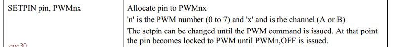 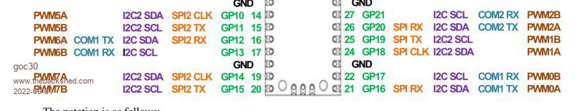 |
||||
| goc30 Guru Joined: 12/04/2017 Location: FrancePosts: 435 |
it work correctly  don't forget declare gp14 as dout |
||||
| matherp Guru Joined: 11/12/2012 Location: United KingdomPosts: 11303 |
RTFM PWM 7,1000,50 |
||||
| goc30 Guru Joined: 12/04/2017 Location: FrancePosts: 435 |
pwm 7A or pwm 7B ????? setpin gp14, PWM7A �???? pulse gp14 Why make it simple when you can make it complicated Edited 2022-06-02 01:07 by goc30 |
||||
| Mixtel90 Guru Joined: 05/10/2019 Location: United KingdomPosts: 8815 |
I think I've got this now... You have to specify both the PWM channel and the pin number a some PWM channels can appear on alternative pins. SETPIN GP14, PWM7A '7A because that's what GP14 can handle 'as PWM7B isn't set up with a SETPIN nothing will happen on it PWM 7, 1000, 50 'output, on PWM7, 1000Hz at 50% duty cycle on channel A I assume tha this would be valid (hardware allowing) and PWM7A not configured: SETPIN GP15, PWM7B PWM 7, 1000, , 50 'output 50% duty cycle on channel B only It's an assumption as I've never driven a B channel alone. Mick Zilog Inside! nascom.info for Nascom & Gemini Preliminary MMBasic docs & my PCB designs |
||||
| matherp Guru Joined: 11/12/2012 Location: United KingdomPosts: 11303 |
Don't know how the manual could be much clearer Edited 2022-06-02 02:21 by matherp |
||||
| goc30 Guru Joined: 12/04/2017 Location: FrancePosts: 435 |
this is only clear to those who wrote the program, but not to those trying to understand this "logic". But hey, you can't be good everywhere. What is unfortunate is for users who have to waste time trying to understand what the programmer meant And above all, let's not forget that this project (MicroMite) is the fruit of passionate amateurs, and not industrialists accustomed to the rigor and seriousness of the profession. So we have to forgive the weaknesses and shortcomings and deal with it. Edited 2022-06-02 03:02 by goc30 |
||||
| matherp Guru Joined: 11/12/2012 Location: United KingdomPosts: 11303 |
The code follows the H/W. Perhaps a little bit of understanding about how the H/W works may help you. The RP2040/Pico manuals are excellent |
||||
| goc30 Guru Joined: 12/04/2017 Location: FrancePosts: 435 |
I'm not sure arrogance is the smartest answer. After 45 years of career in industrial computing and robotics, I think I can teach you much more about the management of PWMs (which I used from 1982 with Intel 8748s and Mosfets) than you would be able to understand. . so come back to more humility. You'll see.. it doesn't hurt!! |
||||
| Mixtel90 Guru Joined: 05/10/2019 Location: United KingdomPosts: 8815 |
Ah - answered on the other thread. I hadn't spotted the double comma. Should have gone to ****Savers. :) Peter's right on this - it's the way the hardware works on the Pico. I know the RP2040 Datasheet is huge, but there's an immense amount of information in it and it's not as difficult to follow as you may think (most of the time!). Just avoid anything that says CPU or PIO on it. ;) I think the main confusion comes in that there are A and B channels on each PWM device. On each device the channels always have the same frequency but the duties are independent. SETPIN relates to a single channel A or B. PWM relates to the PWM device, both channels of it. Consequently, if you want to use A and B channels you need two SETPIN statements. Something that confused me at first. There are actually 8 PWM *devices* available - the frequencies are simply set for each device. It's not a choice of 8 frequencies - which was what I was expecting, coming from a background where the PWM frequencies were derived from a set of dividers. Mick Zilog Inside! nascom.info for Nascom & Gemini Preliminary MMBasic docs & my PCB designs |
||||
| The Back Shed's forum code is written, and hosted, in Australia. | © JAQ Software 2026 |
