
|
|
Forum Index : Microcontroller and PC projects : PicoMite - An extra pin
| Author | Message | ||||
| circuit Guru Joined: 10/01/2016 Location: United KingdomPosts: 305 |
Once an SD1963 screen, touch control, SD card and keyboard have been connected to the PicoMite, there are few interface pins remaining. � Looking at the schematic for the Pi Pico it seems that an extra interface pin can be exposed quite easily by removing the LED and treating Test Point TP5 on the underside as GP25 - easy to solder to. �The connection will be via R3 - a 470R resistor but this can easily be shorted out if needed for the relevant application. � The firmware allows this by using the command SETPIN GP25,DOUT / HEARTBEAT. �The problem with using this is that GP25 will pulse upon bootup until it reaches the command in the program or, more significantly, when the program stops running. It would be much more helpful if there was an OPTION HEARTBEAT ENABLE /DISABLE command available so that the connected device would not be pulsed by default. This syntax would also bring alignment with the HEARTBEAT control in other Micromite versions. If the heartbeat pin was controlled in this way, could other SETPIN configurations be applied to this pin? I note that the RP2040 datasheet lists the GPIO25 functions as; 25 SPI1 CSn UART1 RX I2C0 SCL PWM4 B SIO PIO0 PIO1 CLOCK GPOUT3 USB VBUS DET. When pins are relatively scarce compared with the MicroMite Plus and others, such a modification would be most helpful. Edited 2022-07-14 19:56 by circuit |
||||
| Mixtel90 Guru Joined: 05/10/2019 Location: United KingdomPosts: 8913 |
You could use that pin without disconnecting the LED in some cases. Just remember that a "high" output is only 2V and that output current is a bit limited. It should be fine for driving the base of a small NPN transistor. If you use it as an enable pin for something (with a transistor, so "high" to get a normal, inverted Enable) then it doesn't matter if it's flashing on boot. The first thing you do is to stop it, before the device is initialised by the program. Likewise, on program stop the device isn't getting commands so a flashing enable line probably won't be a problem. Mick Zilog Inside! nascom.info for Nascom & Gemini Preliminary MMBasic docs & my PCB designs |
||||
| circuit Guru Joined: 10/01/2016 Location: United KingdomPosts: 305 |
@Matherp Peter, is there at all the slightest chance of progressing this; I use the Micromite series predominantly for controlling devices - from my home security through to model railways, from CAD-CAM kit to temperature monitoring. Plenty of pins is my priority. The idea of using GP25 on TP5 is utterly tantalising. Yes, of course I can use it as an output but it has limitations that could be removed in your firmware and possibly improved with other functions - even a simple input. The modification to the hardware is minimal - gosh, you could even snip out the LED with a pair of nail clippers let alone a solder iron and be left with an "input" protected with a 470R. I greatly appreciate the vast amount of work that you put in on the firmware and I realise that you cannot accommodate every wish, but it strikes me that this has great gain in function if it could be implemented. Changing the in-line command to an OPTION would match the syntax in the MicroMite Extreme firmware as well, keeping a single syntax across different hardware. |
||||
| Mixtel90 Guru Joined: 05/10/2019 Location: United KingdomPosts: 8913 |
I see your wish has been granted in b15. :) It might be useful for some of the clone boards that bring out more pins too. Mick Zilog Inside! nascom.info for Nascom & Gemini Preliminary MMBasic docs & my PCB designs |
||||
| circuit Guru Joined: 10/01/2016 Location: United KingdomPosts: 305 |
Peter, Many thanks for adding this functionality into b15. It works just as I had hoped. Furthermore, I tried it as a digital input and it works fine. It also works when assigned to PWM Channel 4B as a PWM output. I have not experimented with all the other possible pin attributes such as serial and I2C or other input pin configurations. Could you indicate which of these might be expected to work? At present, I am assuming that this is now just like any other pin. As it is, digital in/out and PWM for servos suits me just fine! Most grateful for your time. |
||||
| Mixtel90 Guru Joined: 05/10/2019 Location: United KingdomPosts: 8913 |
If you connect a red LED directly in parallel with the on-board green one then you'll probably find that the red one takes over from whatever the green one is doing, as Vf for red is lower than Vf for green. :) Mick Zilog Inside! nascom.info for Nascom & Gemini Preliminary MMBasic docs & my PCB designs |
||||
| circuit Guru Joined: 10/01/2016 Location: United KingdomPosts: 305 |
Good point indeed! 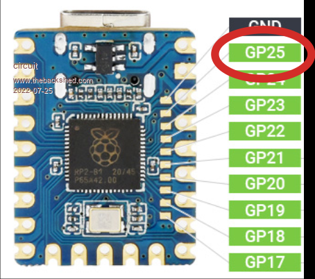 The Waveshare Pi Zero brings GP25 out to a solder pad and benefits from b15. Edited 2022-07-25 03:59 by circuit |
||||
| Mixtel90 Guru Joined: 05/10/2019 Location: United KingdomPosts: 8913 |
I'm not sure that I'd call bringing it out to a pad that only a technological flea with a magnifying glass could solder to is really "bringing it out". :) Mick Zilog Inside! nascom.info for Nascom & Gemini Preliminary MMBasic docs & my PCB designs |
||||
| circuit Guru Joined: 10/01/2016 Location: United KingdomPosts: 305 |
Having hand-soldered the 144 pins at 0.5mm pitch on a Micromite eXtreme (three times so far...five more still in the parts drawer) four 100pin Micromite Plus and other such chips, I can assure you that the pad on the Pi Zero is GIANT by my standards... |
||||
| Mixtel90 Guru Joined: 05/10/2019 Location: United KingdomPosts: 8913 |
Judging by the pic I'd be lucky to *see* them, never mind solder them. :( 1.27mm is plenty small enough for me. I even struggle a bit at 0.1" sometimes now. :( Bring back 25W Solon soldering irons and octal valve bases! Mick Zilog Inside! nascom.info for Nascom & Gemini Preliminary MMBasic docs & my PCB designs |
||||
Grogster Admin Group Joined: 31/12/2012 Location: New ZealandPosts: 9977 |
I have some of those waveshare Pico modules, and thin wires under at LEAST a good magnifying light are a must. I used my microscope, and that made soldering easy, really. Flux the pads, tin them first, tin your wire ends, cut them very short, more flux, tiny bit of solder - done. But I grant you, they are not that easy to do if you don't have a microscope or good illuminated magnifying glass thing. You DO need to use very thin wires, so that you don't put stress on the tiny pads via thicker wires, which can lead to them lifting off the PCB - never a good thing.... I used thin self-fluxing enameled copper winding wire in my experiment with those pads, but you could probably get away with using those coloured "DuPont" leads if you cut off the connector at one end and solder them to the pads. I would not go for anything any thicker though, or just bending the wires around could pull the pads off the PCB. I went looking for pogo-pins small enough to touch on those pads, but the problem always was that the pad width meant that the pads would short-out on the one next to it, cos they are that close together.  I toyed with the idea of a pad on the top layer, and the next one has a pad on the bottom layer, but NOT as vias so to speak. I think that would have worked, but it was starting to get complicated at that point, so I gave up!  Smoke makes things work. When the smoke gets out, it stops! |
||||
bigmik Guru Joined: 20/06/2011 Location: AustraliaPosts: 2981 |
Hi Lads, Could you not solder a 1.27mm Male header onto those pads? It looks the correct spacing and with 10 of them they would help with holding each other fast onto the PCB? Even a small bit of epoxy if you were worried about rigidity? Maybe nip the points off the bottom of each header pin so they sit more flat? Just an idea. Regards, Mick Mick's uMite Stuff can be found >>> HERE (Kindly hosted by Dontronics) <<< |
||||
| Grogster Admin Group Joined: 31/12/2012 Location: New ZealandPosts: 9977 |
Yes, that IS an idea. A good one. The pads DO seem to be 1.27mm apart, and with some epoxy to fortify it.... Yeah, good idea, Mick.  Smoke makes things work. When the smoke gets out, it stops! |
||||
| The Back Shed's forum code is written, and hosted, in Australia. | © JAQ Software 2026 |
