
|
|
Forum Index : Microcontroller and PC projects : PicoPatch
| Author | Message | ||||
| Mixtel90 Guru Joined: 05/10/2019 Location: United KingdomPosts: 8913 |
I've been accused of not leaving enough "sea of holes" areas on my projects in the past. I hope this design rectifies that somewhat. This uses up all the spare holes out of my box. :) 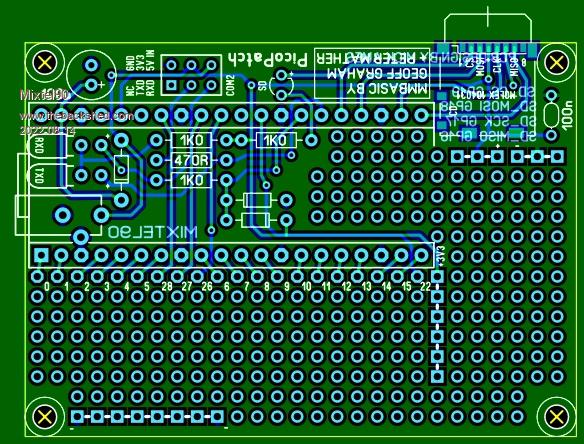 PicoPatch_gerber.zip I don't think it's worth doing a BOM for this. There isn't much circuit either as just about everything is connected to pads. The board is 70mm x 50mm so you can get two out of a 100x100 board. That give you plenty to play with for those little projects that are too wobbly on a breadboard yet don't really merit a proper PCB. The 6-pin connector (intended to be a male header for a Dupont) should really have a polarising arrangement on pin 1, but that isn't easy so the pins are arranged so that things should at least be safe if it's plugged in wrong way round. The board can be powered by this connector or by a 3.5mm barrel jack. The three LEDs are run at low current so it's probably no use using old clunky green or yellow. The micro SD socket is optional, but it's GP pins aren't wired out. Fixing holes are M3 clear. All three diodes should be Schottky types, iA for the supply one and small signal for the two RX clamp diodes. Mick Zilog Inside! nascom.info for Nascom & Gemini Preliminary MMBasic docs & my PCB designs |
||||
| Mixtel90 Guru Joined: 05/10/2019 Location: United KingdomPosts: 8913 |
Circuit: Circuit.pdf Mick Zilog Inside! nascom.info for Nascom & Gemini Preliminary MMBasic docs & my PCB designs |
||||
| The Back Shed's forum code is written, and hosted, in Australia. | © JAQ Software 2026 |
