
|
|
Forum Index : Microcontroller and PC projects : LCD SSD1306 problem
| Author | Message | ||||
| oh3gdo Regular Member Joined: 18/11/2021 Location: FinlandPosts: 47 |
Hey I am quite new in PicoMite projects. I try to put 0.9" SSD1306 LCD to PICO. I open it with OPTION LCDPANEL SSD1306I2C, L, 0 ,or OPTION LCDPANEL SSD1306I2C, L, 1 or OPTION LCDPANEL SSD1306I2C, L, 2 Commands When I write Text 1,1, "Testing 12345" or any other place, I got only upper half of Testing message. I am wondering if I am missing something. I try to find I2C address and got 0x3c, but I can't put it any were. Do anybody has a similar problem? I tried with other LCD, but same result. == I also tried NTC10k as temperature sensor. It has BCoeffient 4000 and reference resistor was also 10k. I got it working, I got about 22C. http://remotesmart.wikidot.com/rasberry-pico-pi-h Pekka |
||||
| Hans Senior Member Joined: 18/10/2022 Location: CanadaPosts: 117 |
Hi Pekka; You are almost there.  I use these options but you may need to adjust for the GP pins you use; option system i2c gp16,gp17 option lcdpanel ssd1306i2c, landscape These options are made at the command line, your PICO will reboot after the 1st option and I am not sure possibly after the 2nd one too. Here is a simple program to display the time on the display. ' BigClock.bas largest font for SSD1306 ' That fits on 128*64 CLS 'This blanks the SSD1306 Display Do ' � Text X,Y,WhatToDisplay$,Landscape,Font #3 Text 0,20,Time$,L,3 Loop I have an RTC on the same I2C bus as the SSD1306 and I used option rtc auto enable to have the date and time read when the PICO starts. My assumption is that it knows the address because of that. 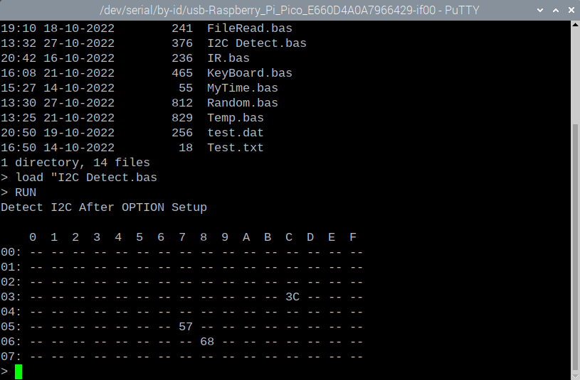 The clock is at H68, Memory at H57 and Display at H3C. The only thing I have to address in a program is the Flash Memory. The rest just works. Good Luck Pekka You can ask lots of questions here, this forum rocks with great support. Hans ...  Edited 2022-10-29 02:28 by Hans |
||||
| oh3gdo Regular Member Joined: 18/11/2021 Location: FinlandPosts: 47 |
Hans, The really fantastic place! Everything works! I had to change I2C commands to GP0 and GP2. But it works. How do you found these? I have an other problem, but I have tried to look it. I took new normal LCD 1602. but it doesn't work. I try to make similar startup program like I have done about 30 years with Microchip CPU. It shows only one row and nothing change when I try BITBANG LCD INIT GP2,GP3,GP4,GP5,GP6,GP7 BITBANG LCD 1,1,"Temp=22" PINs GP0 and GP1 works with my SSD1306 I2C, but PINs GP2-GP7 doesn't go high. I wonder I have broken my PICO? Sub LCD1 SetPin Gp6,dout SetPin GP7,DOUT SetPin GP2,DOUT SetPin GP3,DOUT SetPin GP4,DOUT SetPin GP5,DOUT Pin(GP2)=1 Pin(GP7)=1 Pin(GP2)=0 Pin(GP6)=0 Pin(GP7)=0 Pin(GP2)=1 Pin(GP3)=1 Pin(GP4)=0 Pin(GP5)=0 Pin(GP6)=0 Pin(GP7)=1 ' give pulse Pause 1000 Pin(GP7)=0 ' give pulse Pause 1000 Pin(GP7)=1' give pulse Pause 1000 Pin(GP7)=0' give pulse Pause 1000 Pin(GP7)=1 ' give pulse Pause 1000 End Sub Pekka |
||||
| Hans Senior Member Joined: 18/10/2022 Location: CanadaPosts: 117 |
Hello Pekka; Have a look at page 33 and the top of page 34. I think it explains what you are looking for. This is the MMBasic User manual for version 5.07.04 I am refering to. I have been a business programmer for over 40 years and program in Cobal, RPG, Pascal and Basic. There is no substitute for reading the manual top to bottom. Examples help a lot. There is a code library here in this forum as well. Have a look around. Reading other peoples posts, not just the ones you post, is very handy and insightful to how others code. I that way you learn many fine coding techniques. Personally I bought a board from Amazon to convert the 1602 I have to I2C interface, much easier to use/code for. Hans ... � Edited 2022-10-29 07:19 by Hans |
||||
| oh3gdo Regular Member Joined: 18/11/2021 Location: FinlandPosts: 47 |
Hans Thank you again. but I cant find GP23 or GP GP24 like in the manual. I took GP6 (En) and GP7 (RS) like in the picture. I think this doesn't matter. When I look afterwards my PICO I see some ports 3.3V Hmm, I have to try other lcd. Sub LCD1 Print "lcd" Bitbang LCD INIT GP2,GP3,GP4,GP5,GP6,GP7 Bitbang LCD 1,1," Temp" Bitbang LCD 2,1," 22.35C" Print "LCD done" End Sub Pekka |
||||
| Mixtel90 Guru Joined: 05/10/2019 Location: United KingdomPosts: 8913 |
All ports on the PicoMite are 3V3 - but as outputs from the Pico that's almost always fine for 5V stuff as it's within 5V TTL tolerance. However, you can't connect 5V TTL signals directly back to the PicoMite as you'll damage the inputs. There are ways round this though. In this application RW is grounded so you can't read 5V signals back on the data lines. The Data lines D0-D7, EN and RS are all outputs from the PicoMite (unless you are reading data back from the display - not a common thing to do) so should (in theory anyway) drive most common HD44780-compatible LCD displays. Note that the LCD power might still have to be at 5V though. You can use any of the PicoMite pins, but you must specify them all as DOUT using SETPIN first and then specify them in the BITBANG LCD INIT command. You only need to do these steps once so there's no need to have them in a SUB. Mick Zilog Inside! nascom.info for Nascom & Gemini Preliminary MMBasic docs & my PCB designs |
||||
| oh3gdo Regular Member Joined: 18/11/2021 Location: FinlandPosts: 47 |
Mike I have tried many times, but I cant get my 1602 to working. 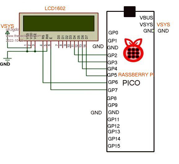 I do not use PICO signals to my LCD. I try write signals to 1 after LCD command, but it can't work. it give errors. This is my sub command. Sub LCD1 Bitbang LCD INIT GP2,GP3,GP4,GP5,GP6,GP7 Bitbang LCD 1,1," Temp" Bitbang LCD 2,1," 22.35C" Print "LCD done" End Sub Hmm, I am done about thee days, but no success. Pekka |
||||
| matherp Guru Joined: 11/12/2012 Location: United KingdomPosts: 11548 |
VEE should be connected to a potentiometer between VSS and VCC. The display may be working but you aren't seeing anything because the contrast is zero |
||||
| oh3gdo Regular Member Joined: 18/11/2021 Location: FinlandPosts: 47 |
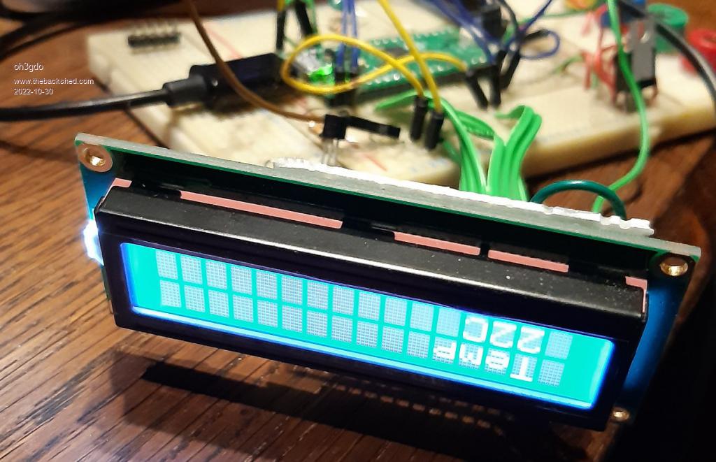 Now I found my problem with my LCD 1602. I was started to put LCD pins from pin 5, although it was should start from pin 4. In the pictures was missing gnd pins, although it should not happend. Thank you who will help me. What I start next? Pekka |
||||
| Mixtel90 Guru Joined: 05/10/2019 Location: United KingdomPosts: 8913 |
I thought you were in Finland? That picture looks like you are in Australia. ;) Glad you got it working. :) matherp is right - if you put a potentiometer of around 1k-5k between GND and 5V with its slider connected to VEE then you can adjust the contrast. Those character positions that you can see can be faded out almost to the point where they can't be seen. start with the slider at mid way and "tune" it to taste. Mick Zilog Inside! nascom.info for Nascom & Gemini Preliminary MMBasic docs & my PCB designs |
||||
| oh3gdo Regular Member Joined: 18/11/2021 Location: FinlandPosts: 47 |
Mixtel90 I am from Finland, from Tampere City. I have worked with electronics more than 50 years. I have been electronics engineer more than 50 years. You can look http://remotesmart.wikidot.com/ like http://remotesmart.wikidot.com/hewlett-packard or http://capacitor.wikidot.com/ I know that normally I need potentiometer or two resistor ( 10k to VCC and 1k to ground), but I was just testing first time PICO programming. Just put LCD oin to ground and you can see how LCD works, I did my first PCB today. Here is schematic I is nothing to work, but I am sure that when can handle PICO more, it will find some work. 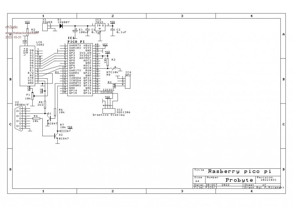 Regards Pekka Ritamaki |
||||
| The Back Shed's forum code is written, and hosted, in Australia. | © JAQ Software 2026 |
