
|
|
Forum Index : Microcontroller and PC projects : 74HC595 display
| Author | Message | ||||
Herry Senior Member Joined: 31/05/2014 Location: AustraliaPosts: 261 |
A long while ago (over 10 years), I built a GPS car speed warning unit for my 30 year old Classic Jag. It displayed speed on a 74HC595 display, not like the 'bare' displays now available. This is a 3 digit model with quite large figures (7 segment of course) housed in a neat black plastic housing that could readily be pressed into an aperture cut into to the font panel of a Jiffy box. Does anyone know where I can purchase another in the same neat housing. The only ones I can find so far are on bare PCs with significantly smaller characters. Senior?! ĀWhatever it says, I'm a complete and utter beginner... |
||||
| Herry Senior Member Joined: 31/05/2014 Location: AustraliaPosts: 261 |
Found it! Electrodragon 2.80 US each! Senior?! ĀWhatever it says, I'm a complete and utter beginner... |
||||
| vegipete Guru Joined: 29/01/2013 Location: CanadaPosts: 1176 |
For those who want more details: LED 7-Segment Display  Visit Vegipete's *Mite Library for cool programs. |
||||
| Volhout Guru Joined: 05/03/2018 Location: NetherlandsPosts: 5923 |
This is even cheaper, also 0.56", and has brightness control... I2C input other option PicomiteVGA PETSCII ROBOTS |
||||
Grogster Admin Group Joined: 31/12/2012 Location: New ZealandPosts: 9975 |
Yes, I had a handful of these displays a few years ago. From what I remember, you use an SPI channel to load the data, and another pin as the latch line to make the display show the data. Quick, simple and easy.  Smoke makes things work. When the smoke gets out, it stops! |
||||
| Herry Senior Member Joined: 31/05/2014 Location: AustraliaPosts: 261 |
I'm looking at the software I developed to run that GPS indicator for the car about 2 or so years ago, which made use of SPI to display on the 74HC595. Although I wrote it, part of it no longer make any sense to me (programmer's curse). It makes use of a table of characters (based on their ASCIIs) and works. This is part of it DISP(48)=&B00111111 '0 DISP(49)=&B00000110 '1 DISP(50)=&B01011011 '2 DISP(51)=&B01001111 '3 DISP(52)=&B01100110 '4 '.... Ā Clearly the array holds coding to display the characters 1, 2, 3 Āand the position in the array is the ASCII for those characters but I can't relate it to the binary code. The device works and I know that the code must have been logical because I wrote it when only 80! Edited 2022-11-06 10:42 by Herry Senior?! ĀWhatever it says, I'm a complete and utter beginner... |
||||
| phil99 Guru Joined: 11/02/2018 Location: AustraliaPosts: 3289 |
My guess at the bit numbers for the segments to match your code. Ā Ā Ā Ā __1__ Ā LSB = 1, ĀMSB = 8 = DP (if it has a decimal point) Ā Ā Ā Ā/ Ā Ā/ Ā Ā 6 / Ā Ā/ 2 Ā Ā Ā__7__ Ā Ā / Ā Ā/ Ā5 / Ā Ā/ 3 Ā __4__ Ā o8 . Edited 2022-11-06 11:15 by phil99 |
||||
| Herry Senior Member Joined: 31/05/2014 Location: AustraliaPosts: 261 |
Can you please relate that to say the first binary string in my post? Senior?! ĀWhatever it says, I'm a complete and utter beginner... |
||||
| Herry Senior Member Joined: 31/05/2014 Location: AustraliaPosts: 261 |
Thanks Phil99, no further reply needed. That was it! I can see now that the bits are read in reverse order and correspond to the segment numbers as per your diagram! Senior?! ĀWhatever it says, I'm a complete and utter beginner... |
||||
| phil99 Guru Joined: 11/02/2018 Location: AustraliaPosts: 3289 |
Though you don't need this here it is anyway. __1__ LSB = 1, MSB = 8 = DP (if it has a decimal point) 1=2,3 &B00000110 6 / / 2=1,2,4,5,7 &B01011011 91 6 / / 2 3=1,2,3,4,7 &B01001111 79 __7__ 4=2,3,6,7 &B01100110 102 / / 5=1,3,4,6,7 &B01101101 109 5 / / 3 6=3,4,5,6,7 &B01111100 124 __4__ o8 7=1,2,3 &B00000111 7 8=1,2,3,4,5,6,7 &B01111111 127 9=1,2,3,6,7 &B01100111 103 0=1,2,3,4,5,6 &B00111111 63 DP=8 ADD TO ABOVE &B10000000 128 |
||||
| Herry Senior Member Joined: 31/05/2014 Location: AustraliaPosts: 261 |
Yup. A 1 bit is segment alight and a 0 bit is off, going clockwise from the top as you numbered. The string must be read in reverse. The decimal translation of the stream of bits is really a red herring and misled me. Edited 2022-11-06 17:35 by Herry Senior?! ĀWhatever it says, I'm a complete and utter beginner... |
||||
| Martin H. Guru Joined: 04/06/2022 Location: GermanyPosts: 1459 |
and with a little imagination, you'll also get Test: 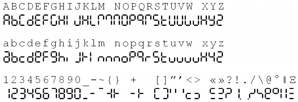 ok for M Āand W you will need 2 Digits  a little helper for Excel or Libre Office 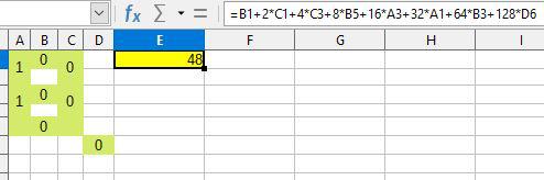 7segment.zip Edited 2022-11-06 19:46 by Martin H. 'no comment |
||||
| oh3gdo Regular Member Joined: 18/11/2021 Location: FinlandPosts: 47 |
Hey, I did motor speed display about 1976. It shows also battery voltage and the percentage of car breaker tips. I worked very well and it was a good help when I was fishing at winter. It was about -20C Temperature. My car doesn't start. Looked the meter and I see that the breaker tips was changing between 0 or 100%. It should be about 62%. I had an old breaker tips in my car and I changed old tips. My car stated normally. Second times when I was traveling in Sweden (I am from Finland) and I stopped to get gas. After that my car can't start. I asked help from gas salesmen. They measure my car battery and it was about 8V. They sell a new battery to me. It was about two times more money than in Finland. When I started I saw from voltmeter that the battery voltage is about 12V. It should be about 14.2V. Now I knew that my charger is gone. When I open car engine hatch and looked my charger's belt, it was stretchy. I asked the salesmen if they have a new belts, but they said that they only sell batteries. They took my new battery off and advised where is the nearest Toyota dealer. I live my car running, when they remove the battery and I found the Toyota dealer and I got new belt. Then I went to Germany for the holiday. What was the reason? At this time Finland has no forced light on order also in daytime, but in Sweden it was on. Here is the schematic http://remotesmart.wikidot.com/digitest Pekka |
||||
| phil99 Guru Joined: 11/02/2018 Location: AustraliaPosts: 3289 |
Another way to drive these displays, or any SN74HC595N chips and save a pin or two. SPI requires a Rx pin even though it isn't needed here and a fourth pin is used for the storage register clock. And a fifth pin for CS if SPI is shared. This circuit provides the storage register clock when the shift register clock pauses between transmissions. Any two PicoMite pins can be used. HC595 pins 16 & 10 to 3V3, 8 & 13 to 0V. 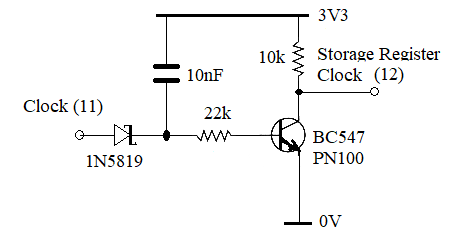 Ā Ā Ā Ā__1__ Ā LSB = 1, ĀMSB = 8 = DP (if it has a decimal point) Ā0=1,2,3,4,5,6 Ā Ā&B00111111 Ā Ā 63 Ā Ā Ā / Ā Ā/ Ā Ā Ā Ā Ā Ā Ā Ā Ā Ā Ā Ā Ā Ā Ā Ā Ā Ā Ā Ā Ā Ā Ā Ā Ā Ā Ā 1=2,3 Ā Ā Ā Ā Ā Ā&B00000110 Ā Ā 6 Ā Ā6 / Ā Ā/ 2 Ā Ā Ā Ā Ā Ā Ā Ā Ā Ā Ā Ā Ā Ā Ā Ā Ā Ā Ā Ā Ā Ā Ā Ā Ā Ā Ā2=1,2,4,5,7 Ā Ā Ā&B01011011 Ā Ā 91 Ā Ā __7__ Ā Ā Ā Ā Ā Ā Ā Ā Ā Ā Ā Ā Ā Ā Ā Ā Ā Ā Ā Ā Ā Ā Ā Ā Ā Ā Ā Ā Ā3=1,2,3,4,7 Ā Ā Ā&B01001111 Ā Ā 79 Ā Ā/ Ā Ā/ Ā Ā Ā Ā Ā Ā Ā Ā Ā Ā Ā Ā Ā Ā Ā Ā Ā Ā Ā Ā Ā Ā Ā Ā Ā Ā Ā Ā Ā4=2,3,6,7 Ā Ā Ā Ā&B01100110 Ā Ā 102 5 / Ā Ā/ 3 Ā Ā Ā Ā Ā Ā Ā Ā Ā Ā Ā Ā Ā Ā Ā Ā Ā Ā Ā Ā Ā Ā Ā Ā Ā Ā Ā Ā 5=1,3,4,6,7 Ā Ā Ā&B01101101 Ā Ā 109 Ā__4__ Ā o8 Ā Ā Ā Ā Ā Ā Ā Ā Ā Ā Ā Ā Ā Ā Ā Ā Ā Ā Ā Ā Ā Ā Ā Ā Ā Ā Ā Ā6=3,4,5,6,7 Ā Ā Ā&B01111100 Ā Ā 124 Ā Ā Ā Ā Ā Ā Ā Ā Ā Ā Ā Ā Ā Ā Ā Ā Ā Ā Ā Ā Ā Ā Ā Ā Ā Ā Ā Ā Ā Ā Ā Ā Ā Ā7=1,2,3 Ā Ā Ā Ā Ā&B00000111 Ā Ā 7 Ā Ā Ā Ā Ā Ā Ā Ā Ā Ā Ā Ā Ā Ā Ā Ā Ā Ā Ā Ā Ā Ā Ā Ā Ā Ā Ā Ā Ā Ā Ā Ā Ā Ā8=1,2,3,4,5,6,7 Ā&B01111111 Ā Ā 127 Ā Ā Ā Ā Ā Ā Ā Ā Ā Ā Ā Ā Ā Ā Ā Ā Ā Ā Ā Ā Ā Ā Ā Ā Ā Ā Ā Ā Ā Ā Ā Ā Ā Ā9=1,2,3,6,7 Ā Ā Ā&B01100111 Ā Ā 103 Ā Ā Ā Ā Ā Ā Ā Ā Ā Ā Ā Ā Ā Ā Ā Ā Ā Ā Ā Ā Ā Ā Ā Ā Ā Ā Ā Ā Ā Ā Ā Ā ĀDP=8 ADD TO ABOVE Ā&B10000000 Ā Ā 128 EDIT After devising a method of also getting the shift-register clock from pulse width modulating the data I found it had been done better before by getting the data from the PW modulated clock.. See here:- www.RomanBlack.com/shift1.htm  His method for getting the latch pulse sacrifices a data bit. Adding one diode fixes that and no longer needs a separate latch pulse (the separate latch pulse uses a data bit). Adding another diode to the data line allows it to run faster, by instantly recharging the timing capacitor.  These are the results. 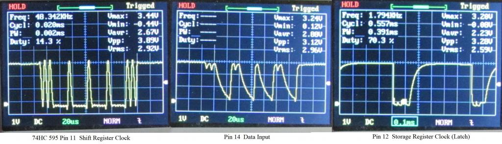 Here is a console command line prog. to demonstrate. One chip clear : pin(4)=1 : setpin 4, dout : dim integer C=1, B(C*16-1) 'C = number of 74HC595 chips chained, B=Bitstream array. 'count up > do:for n=0 to (C*8-1):B(n*2)=25-(w>>(C*8-n) and 1)*22:B(1+n*2)=5:next:BITBANG BITSTREAM 4,C*16,B():inc w :loop > w=2^(c*8) 'count down > do:for n=0 to C*8-1:B(n*2)=25-(w>>(C*8-1-n) and 1)*22:B(1+n*2)=5:next:BITBANG BITSTREAM 4,C*16,B():inc w,-1:loop Four chips clear : pin(4)=1 : setpin 4, dout : dim integer C=4, B(C*16-1) 'C = number of 74HC595 chips chained, B=Bitstream array. 'count up > do:for n=0 to (C*8-1):B(n*2)=25-(w>>(C*8-n) and 1)*22:B(1+n*2)=5:next:BITBANG BITSTREAM 4,C*16,B():inc w :loop > w=2^(c*8) 'count down > do:for n=0 to C*8-1:B(n*2)=25-(w>>(C*8-1-n) and 1)*22:B(1+n*2)=5:next:BITBANG BITSTREAM 4,C*16,B():inc w,-1:loop Data Pin 14 - 3n3 to gnd, 3k3 to CK, diode cathode, anode to CK - Pin 11 Latch Pin 12 3n3 to gnd, 10k to CK, diode anode, cathode to CK Ā- Pin 11 Another EDIT When first powered up there can be some random output. This circuit holds the Not Output Enable pin (13) high until you have initialized the chips with all low, all high or whatever startup state you require. 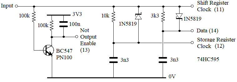 Here is some test code for a 4 digit display. HC595 pins 16 & 10 to 3V3, 8 to 0V. 'One pin drive for SN74HC595 chips. Dim integer dp=4, C=4, B(C*16-1) ,TI=C*16-1, n, word ':Print Bin$(word,C*8) 'word = data to send Ā' dp = data pin, TI = Time intervals, C = number of 74HC595 chips chained, B = Bitstream array. Ā' When dp first goes high outputs are high Z for 3mS to allow time for initialization Ā' 2uS to 5uS low = 1, >22uS low = 0 and >50uS high = latch clock Ā' Set all bits high or low before outputs become active. ĀHC595 dp, C, C*0 'Call Sub with DataPin, number of Chips, Word to send, 0=all low, C*256-1=all high ĀPause C For n=24 to 0 step -8 Āword = 1987655743>>n ĀHC595 dp, C, word 'Call Sub with DataPin, number of Chips, Word to send. ĀPause 1000 Next Pause 3000 Dim integer LT(11)=(63,6,91,79,102,109,124,7,127,103,128,0) 'Lookup table LT(11)=blank word = 0 For n=0 To 9 Ā word = (word<<8 And (2^32-1)) + LT(n) ĀPrint n, Bin$(word,32), word Ā ĀHC595 dp, C, word Ā ĀPause 2000 Next Sub HC595 dp As integer, C As integer, input As integer 'DataPin, number of Chips, Word to send. ĀPin(dp)=1 ĀLocal integer n, B(C*16-1), TI=C*16-1 ĀFor n=0 To TI Step 2 Ā B(n)=25-(input>>(TI-n)\2 And 1)*22 'low data pulses Ā B(n+1)=5 'high spaces ĀNext ĀBitbang BITSTREAM dp, C*16, B() 'send it ĀPause C End Sub The Bitstream times are chosen to suit the R-C values in the diagram. Yet Another Edit The Pico doesn't have many ADC input pins and the PicoMiteVGA with all extras fitted doesn't have all that many pins left. This gives you another 3 analogue (or digital) inputs and 3 more digital outputs. In this example the 74HC595's 4 low outputs expand one Pico output and the upper 4 outputs drive a CD4066 quad analogue switch IC to expand one analogue input. The 4 analogue inputs are read one at a time and displayed via LEDs as integer values on the 4 low outputs. Not useful just a hint at what can be done. Connect 4066 input 1 to 0V, !k from 1 to 2, 1k from 2 to 3, 1k from 3 to 4 and 4 to 3V3 and the LEDs will light in sequence. 74HC595 pin 15, bit 0 = 0v pin 1, bit 1 = 1v pin 2, bit 2 = 2v pin 3, bit 3 = 3v 'Four position analogue switch plus four digital outputs using two Pico pins Dim integer Ādp=4, ap=31, C=1, Vin, Led, n, W 'dp = data out pin, ap = annalogue in pin, C= No. of 74HC595 chips. Pin(dp) = 1 : SetPin dp,dout : SetPin ap, ain Do ĀFor n=0 To 3 Ā W = 16 * 2^n Ā'Select input switch position Ā HC595 4,1,W Ā 'activate switch Ā Vin = Int(Pin(ap)) 'Read the voltage Ā Led = 2^Vin 'Convert voltage to LED number Ā W = 16 * 2^n + Led Ā HC595 4,1,W 'Output the voltage on LEDs 0 - 3 Ā Pause 2000 ĀNext Loop Sub HC595 dp As integer, C As integer, input As integer ' Ā Ā Ā Ā DataPin, Ā Ā number of Chips, Word to send. ĀPin(dp)=1 ĀLocal integer n, B(C*16-1), TI=C*16-1 ĀFor n=0 To TI Step 2 Ā B(n)=25-(input>>(TI-n)\2 And 1)*22 'low data pulses Ā B(n+1)=5 'high spaces ĀNext ĀBitbang BITSTREAM dp, C*16, B() 'send it ĀPause C End Sub 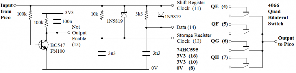 . Edited 2022-11-27 06:29 by phil99 |
||||
| The Back Shed's forum code is written, and hosted, in Australia. | © JAQ Software 2026 |
