
|
|
Forum Index : Microcontroller and PC projects : Anyone interested in lab power supplies?
| Author | Message | ||||
| Mixtel90 Guru Joined: 05/10/2019 Location: United KingdomPosts: 8911 |
This design has been a bit of entertainment for me for day or three. It's for a lab quality power supply, nothing fancy but hopefully it should do the right things reasonably well. In common with many modern supplies the front end is entirely digital, using a RP2040-Zero for the embedded computing and a ILI9341 for control and instrumentation. Circuit: mini PSU 01.pdf It's a completely linear supply to keep electrical noise down, with digital and analogue circuits on separate PCBs that are stacked together. It's intended to be cased and, in theory, will fit into a case about 110mm wide x110mm high x 150mm deep. To manage that I intend to use a CPU cooler heatsink & fan. It should handle it easily as the maximum dissipation is only about 25W. This isn't a high output supply! To achieve that the input voltage to the regulator can be switched, so below 9V it is halved. Output should be 2A up to 9V then 1A from 9V to 18V. I've designed some PCBs for it and they *should* be ok, but I've not tested everything. Don't expect me to rush to make this. I'm notorious for designing power supplies that don't get built. TBH, I'm a little more tempted by this one as it's a manageable size and it has a PicoMite in it. :) Whether it's worth even considering building it is something else. I can get a perfectly usable ready built "Duratool" one from CPC for about 35UKP and the transformer alone for this would be about 16UKP. 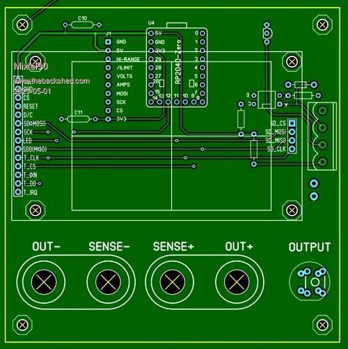 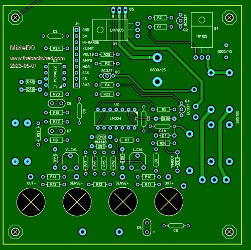   Edited 2023-05-01 01:57 by Mixtel90 Mick Zilog Inside! nascom.info for Nascom & Gemini Preliminary MMBasic docs & my PCB designs |
||||
| Volhout Guru Joined: 05/03/2018 Location: NetherlandsPosts: 5936 |
Hi Mick, At first glance D15 needs to be a shottky diode. The voltage loop gain seems very high, I expect stability problems. Maybe a resistor in the emitter of Q4? U2 is powered from 12V, but its inputs U2-3 can be 10v. Is that okay? Volhout Edited 2023-05-01 05:47 by Volhout PicomiteVGA PETSCII ROBOTS |
||||
| Mixtel90 Guru Joined: 05/10/2019 Location: United KingdomPosts: 8911 |
Agreed on your first two points. Loop gain is pretty high. Luckily Q5 has neither very high gain nor very high speed, I don't think. :) Yep, an emitter resistor for Q4 is a good idea - I can always capacitor bypass it to trim things. Ah - the differential amp... The LM324 top end of the differential input voltage is VCC-1.7V so I think it will probably survive. lol. Do you think it would be better powered from 24V? It can run off up to 32V. 12V just happened to be handy and it would give me some flexibility for increasing the transformer voltage to 12-0-12 (no longer safe for the LM324). Mick Zilog Inside! nascom.info for Nascom & Gemini Preliminary MMBasic docs & my PCB designs |
||||
| Amnesie Guru Joined: 30/06/2020 Location: GermanyPosts: 757 |
I can only speak for me, but I would love to see a lab bench PSU driven by MMBASIC! Greetings Daniel |
||||
| Mixtel90 Guru Joined: 05/10/2019 Location: United KingdomPosts: 8911 |
You can be the guinea pig and build one if you like, Daniel. :) As Volhout said though, no guarantees about stability. You almost always need to tweak them. I've just done a couple of mods. If all the components are mounted on the front of the analogue PCB then you can use 50mm spacers to join it tp the front one, and wire links or something for J2. You can also put Q5 standing up at the back of the board with a small heatsink. This arrangement should be ok for experimentation up to 100mA or so, just to iron out early problems. The holes below the display take standard terminals. Edited 2023-05-01 07:14 by Mixtel90 Mick Zilog Inside! nascom.info for Nascom & Gemini Preliminary MMBasic docs & my PCB designs |
||||
| Volhout Guru Joined: 05/03/2018 Location: NetherlandsPosts: 5936 |
@Mick, Additionally I would make this modification. Just to cope with stability problems: 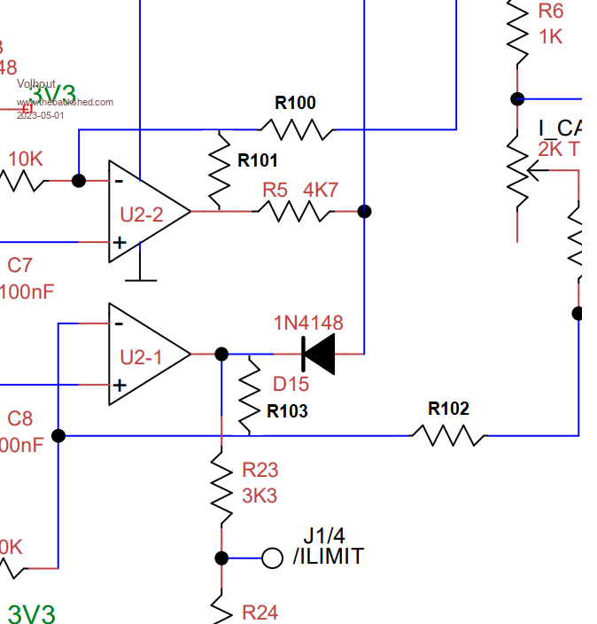 R100/R102 can be 0 ohm to achieve your circuit. In case of stability probelms you can change R100 and R102 into 10k or so, and R101 and R103 ino either capacitors (roll-off) or into resistors (limit gain). Regards Volhout Edited 2023-05-01 18:23 by Volhout PicomiteVGA PETSCII ROBOTS |
||||
| JohnS Guru Joined: 18/11/2011 Location: United KingdomPosts: 4336 |
Got a link please? (I couldn't find anything like that price.) John Edited 2023-05-02 23:21 by JohnS |
||||
| Mixtel90 Guru Joined: 05/10/2019 Location: United KingdomPosts: 8911 |
https://cpc.farnell.com/search?st=duratool%20power%20supplies&gs=true I don't think I'm going to bother building one. It's probably not worth the hassle at these prices. CPC give free postage over 20UKP (plus vat) too. They do a lot of other PSUs. These are the cheap ones. :) Mick Zilog Inside! nascom.info for Nascom & Gemini Preliminary MMBasic docs & my PCB designs |
||||
| IanRogers Senior Member Joined: 09/12/2022 Location: United KingdomPosts: 152 |
https://cpc.farnell.com/duratool/d03233/power-supply-1ch-18v-3a-adjustable/dp/IN08000 Cheers for that Mick... It is a very good price... I'd give my left arm to be ambidextrous |
||||
| JohnS Guru Joined: 18/11/2011 Location: United KingdomPosts: 4336 |
Thanks, Mick - don't know why I couldn't find that! John |
||||
| Mixtel90 Guru Joined: 05/10/2019 Location: United KingdomPosts: 8911 |
I might not be building a PSU, but I've had some fun putting this design together over the last couple of days. I did it primarily to try out EasyEDA - which I'm starting to like. It's definitely a better system than Sprint Layout 6 and TinyCAD, but it's not as fast to use. Highly recommended so far. I've not attempted to create my own components yet so I've no idea how difficult that is. It'll have a job to beat Sprint Layout for that. 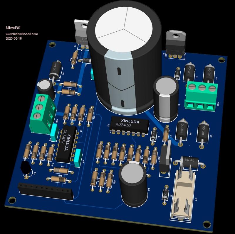 Mick Zilog Inside! nascom.info for Nascom & Gemini Preliminary MMBasic docs & my PCB designs |
||||
| Mixtel90 Guru Joined: 05/10/2019 Location: United KingdomPosts: 8911 |
I'm not sure if this pic belongs here or on the workshop thread! However, I've finally got a bench power supply that's small enough at 100mm wide and 80mm deep. :) 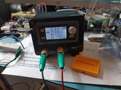 All the clever stuff is in a single Chinese module from ebay. I've added a 7508 regulator to feed a USB socket and a sort of temperature controlled fan that still needs work on it. :) It's a buck-boost converter and is powered from a 19V power brick. Max output is 30V, min is 0.6V and it can dissipate 35W according to the spec (not tested). I'm still getting the hang of the control system, which is slightly weird as expected. Seems to work quite nicely but is a bit "sluggish". I get the feeling that there is too much capacitance across the output, but hey, what do you expect for that price? It beats any LM317 design for flexibility hands down. Edited 2023-05-28 18:20 by Mixtel90 Mick Zilog Inside! nascom.info for Nascom & Gemini Preliminary MMBasic docs & my PCB designs |
||||
| lizby Guru Joined: 17/05/2016 Location: United StatesPosts: 3784 |
Nice build-out. I have and like the module (for the same reason--space occupied), but haven't customized it. PicoMite, Armmite F4, SensorKits, MMBasic Hardware, Games, etc. on FOTS |
||||
| Mixtel90 Guru Joined: 05/10/2019 Location: United KingdomPosts: 8911 |
I had an even smaller version (just the front half of this box) with a different module but there was no cooling and I eventually bricked the module by accidentally setting OVP to zero. Now I can't even get to the settings screen to fix it! No great loss as the text was tiny and setting things was a pain. I'm now considering re-using the case and fitting a different insides to make a general purpose audio oscillator of some sort. Mick Zilog Inside! nascom.info for Nascom & Gemini Preliminary MMBasic docs & my PCB designs |
||||
| Volhout Guru Joined: 05/03/2018 Location: NetherlandsPosts: 5936 |
Hi Mick, Just thinking about your idea for a pico based power supply. I know you are already equipped, but I wanted to share this photo. It is of a cheap chineese LM2596 design (this is with display, but I essentially need one without) that is a pre-regulator for an LM317. It makes sure there is 3V across the 317, so even at 1A it dissipates only 3W. Tracking works nice. Only the chineese (3A specification) circuit gets warm at 1A. Input capacitor, output capacitor, inductor, and switcher IC. The ripple at the switcher output is 4Vpp (at 1A !). I am glad there is an LM317 to filter this. The LM317 produces 10.016V at 1A in below test. The ugly big inductor is just a test. This will become as 10mm one. 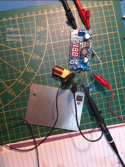 I plan on using the 4822 DAC, same as you. So there will be an LM358 added, and adjustable current limit, Volhout Edited 2024-12-03 06:57 by Volhout PicomiteVGA PETSCII ROBOTS |
||||
| Glen0 Senior Member Joined: 12/10/2014 Location: New ZealandPosts: 101 |
Nice one Mick Yes, stability is always an issue and tweaking in the control line is almost always necessary, particularly around the current limit portion. I like your control line approach around Q4, U2-1 and U2-2. I hope to adapt this into a higher voltage power supply (60V). I have been experimenting with the power supply design shown in the Renesas CA3240 op amp data sheet and have moved the current sense to the high-side by using an INA280 amplifier which has a very handy 1MHz bandwidth. This of course limits me to about 30V out. Watching this thread with interest. Thanks for sharing. Glen |
||||
| Mixtel90 Guru Joined: 05/10/2019 Location: United KingdomPosts: 8911 |
Sheesh... I'd completely forgotten about this thread. :) I never took the design any further, in fact I don't use a PSU much anyway as most things are happy with either a 12V "brick" or a 5V USB power bank. Current limiting is always the issue though, that's what rules out the myriad of LM317 designs (well, that and the fact that it's a horrible chip for a variable PSU). I have one though, supposedly an educational unit for kids to use and the circuit design is vile. Thermal considerations? What are they? lol Mick Zilog Inside! nascom.info for Nascom & Gemini Preliminary MMBasic docs & my PCB designs |
||||
| PhenixRising Guru Joined: 07/11/2023 Location: United KingdomPosts: 1961 |
Holy moly, Mick, I totally missed this thread. Your 3d model is super-impressive  I for one, am interested in DIY power-supplies  |
||||
| Mixtel90 Guru Joined: 05/10/2019 Location: United KingdomPosts: 8911 |
It's EasyEDA that does the really clever 3D stuff. :) You can zoom in and move round the board to get different views. Sometimes the components aren't particularly helpful - like when the only 14DIP package is labelled XD74LS7. :) Mick Zilog Inside! nascom.info for Nascom & Gemini Preliminary MMBasic docs & my PCB designs |
||||
| The Back Shed's forum code is written, and hosted, in Australia. | © JAQ Software 2026 |
