Notice. New forum software under development. It's going to miss a few functions and look a bit ugly for a while, but I'm working on it full time now as the old forum was too unstable. Couple days, all good. If you notice any issues, please contact me.
dddns Guru Joined: 20/09/2024 Location: GermanyPosts: 843
Posted: 06:58am 08 Jul 2025
Copy link to clipboard
Print this post
Maybe the good old "Nokia" display could be an option as it IIRC does not need to be backlit in daylight and could display graphs, but I really don't know its specs and power consumption.
Nice work! Best wishes
zeitfest Guru Joined: 31/07/2019 Location: AustraliaPosts: 683
Posted: 02:01pm 08 Jul 2025
Copy link to clipboard
Print this post
I did try running the (old) lcd on the 3.3v, but there was no visible output. Some modules will display OK on the 3.3v apparently but others not. The backlight led is ok on 3.3v, and the processing might run, but the glass logic levels need more juice.
Frank N. Furter Guru Joined: 28/05/2012 Location: GermanyPosts: 1102
Posted: 06:28am 09 Jul 2025
Copy link to clipboard
Print this post
@zeitfest:
Are you sure that it is not due to the negative contrast voltage? I had the same problem. It worked with this circuit here: https://elm-chan.org/docs/lcd/lcd3v.html
I have realised the PWM with the Picomite and can now set the contrast via the duty cycle (or was it the frequency? ). In any case, the display didn't show anything at all before with 3V3, now it works...
Frank Edited 2025-07-09 18:09 by Frank N. Furter
zeitfest Guru Joined: 31/07/2019 Location: AustraliaPosts: 683
Posted: 11:46am 10 Jul 2025
Copy link to clipboard
Print this post
That looks like the best solution . Though, as it turns out I can get ridiculously cheap boost modules and the 5v will be useful for future growth so that's the way for now.
zeitfest Guru Joined: 31/07/2019 Location: AustraliaPosts: 683
Posted: 03:52am 23 Jul 2025
Copy link to clipboard
Print this post
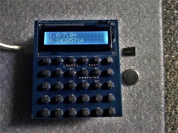
The "budget" version on two stacked pcbs, running calculator script off the sdmicro. The 4x4 size pcbs are a lot cheaper but the display is limited It has space for a lipo. Also circuitry for the RTC but I have !@#$% lost the ic for it so have get some more before I can test that.


 ).
). .
. 
 so have get some more before I can test that.