
|
|
Forum Index : Microcontroller and PC projects : hdmi breakout board
| Author | Message | ||||
| stanleyella Guru Joined: 25/06/2022 Location: United KingdomPosts: 2807 |
I ordered one of these. https://thepihut.com/products/adafruit-dvi-breakout-board-for-hdmi-source-devices it suggests using GP12 to D0+ GP13 to D0- GP14 to CK+ GP15 to CK- GP16 to D2+ GP17 to D2- GP18 to D1+ GP19 to D1- how do the D0+ etc. relate to the board labelsplease if any ideas? going to make pico 2350 usb hdmi sound and sdcard cheers, stan |
||||
| Martin H. Guru Joined: 04/06/2022 Location: GermanyPosts: 1459 |
I connected the HDMI module according to this plan 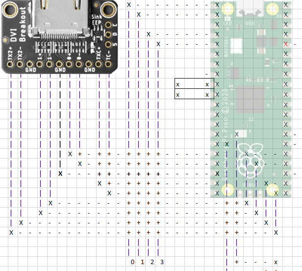 sorry, I just had Excel to draw the design and ignore the other lines Edited 2024-11-19 05:14 by Martin H. 'no comment |
||||
| Mixtel90 Guru Joined: 05/10/2019 Location: United KingdomPosts: 8911 |
TX2+ = D2+ TX2- = D2- 1+ = D1+ 1- = D1- 0+ = D0+ 0- = D0- TXC+ = CK+ TC- = CK- You should also connect "5" to 5V. You'll also need GND, of course. Mick Zilog Inside! nascom.info for Nascom & Gemini Preliminary MMBasic docs & my PCB designs |
||||
| stanleyella Guru Joined: 25/06/2022 Location: United KingdomPosts: 2807 |
Thanks Martin and Mick. great help for me. I got one pico2 2350 left from 4 and stripboard a hdmi usb mmbasic compatible with sd card reader and audio. The olimex board was too good to be true. |
||||
| stanleyella Guru Joined: 25/06/2022 Location: United KingdomPosts: 2807 |
If I use this from the manual config suggestion and works vga usb OPTION SERIAL CONSOLE COM2,GP8,GP9 OPTION SDCARD GP13, GP10, GP11, GP12 OPTION AUDIO GP0,GP1', ON PWM CHANNEL 0 Gp14=pin19 Gp15=pin20 Gp16=pin21 Gp17=pin22 Gp18=pin24 Gp19=pin25 Gp20=pin26 Gp21=pin27 would OPTION HDMI PINS 19, 21, 26, 24 work or I got it wrong? |
||||
| stanleyella Guru Joined: 25/06/2022 Location: United KingdomPosts: 2807 |
got a hdmi breakout board but not a clue. used Micks suggested but not wired 5V. is it the hole marked 5? happy daze.stan 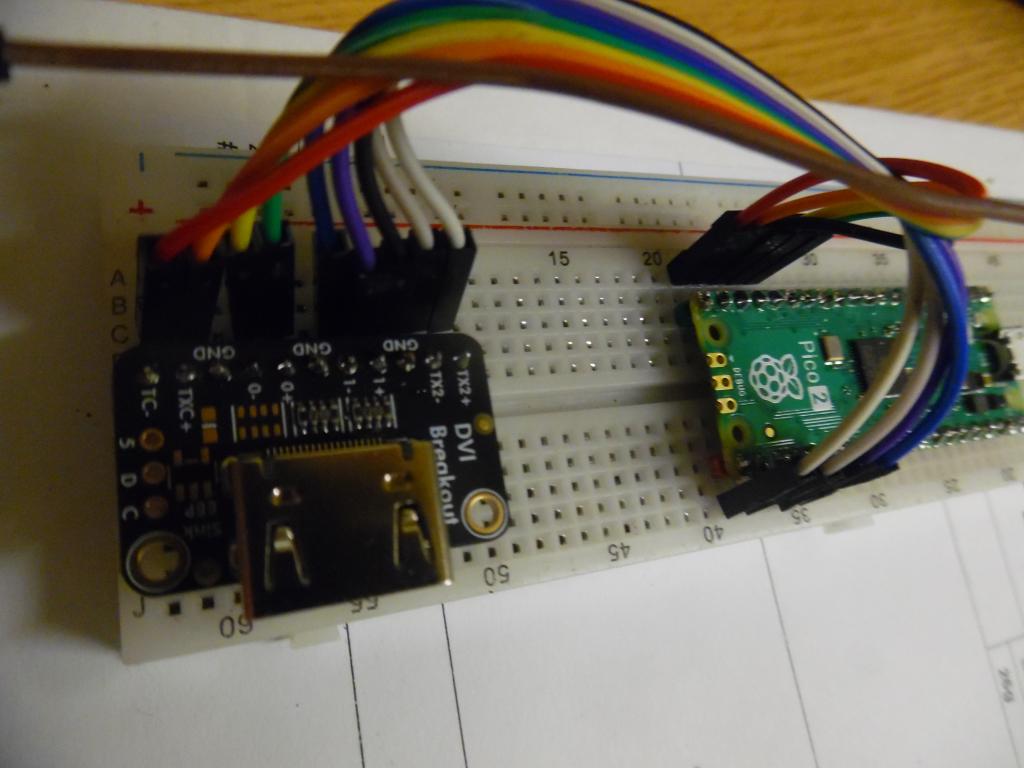 |
||||
| Mixtel90 Guru Joined: 05/10/2019 Location: United KingdomPosts: 8911 |
Yes. The 5V signal is to tell the monitor that there is a HDMI device connected. It's not always used, but some displays insist on it. You also have to be running a HDMI version of MMBasic, of course. Nothing else will work. The numbers in the OPTION HDMI command are the HSTX port bit numbers. They have nothing to do with pin numbers on anything or GP numbers. . Edited 2024-11-22 08:25 by Mixtel90 Mick Zilog Inside! nascom.info for Nascom & Gemini Preliminary MMBasic docs & my PCB designs |
||||
| stanleyella Guru Joined: 25/06/2022 Location: United KingdomPosts: 2807 |
Good news option hdmi pins 2,0,6,4 worked with gp12=0+ gp13=0- gp14=txc+ gp15=tc- gp16=tx2+ gp17=tx2- gp18=1+ gp19=1- this the pihut dvi breakout board pin labels. well pleased it works. option list doesn't show option hdmi pins x,x,x,x 5V to hdmi wasn't needed. PicoMiteHDMI MMBasic Version 6.00.00RC15 OPTION FLASH SIZE 4194304 OPTION KEYBOARD US OPTION CPUSPEED (KHz) 315000 I want to use hdmi usb and serial usb to ttl for windows and sd card and audio but using these hdmi gp pins problems maybe. thanks all for help, stan Edited 2024-11-23 04:53 by stanleyella |
||||
| Mixtel90 Guru Joined: 05/10/2019 Location: United KingdomPosts: 8911 |
You don't have a choice of HSTX pins. They are fixed by the Pico hardware. You'll just have to work around them. :) OPTION LIST won't show the pin arrangement for the HSTX. I suspect that's because it can't be read back, but I may be wrong. The usual way is to use GP8 and GP9 for a USB-TTL converter to give the 5V supply and connection to the console. The serial port speed is 115200 baud by default. USB is via the USB port on the Pico, of course. You can't use it for the console or power when using the USB version of MMBasic. The SD card can be on any pins. Mick Zilog Inside! nascom.info for Nascom & Gemini Preliminary MMBasic docs & my PCB designs |
||||
| matherp Guru Joined: 11/12/2012 Location: United KingdomPosts: 11523 |
It will if it is non-standard |
||||
| stanleyella Guru Joined: 25/06/2022 Location: United KingdomPosts: 2807 |
option sdcard gp22,gp6,gp7,gp4 works with the hdmi and reads files option audio gp26,gp27 is accepted but not tested > option serial console gp8,gp9 Error : Pin 11/GP8 is in use where? PicoMiteHDMI MMBasic Version 6.00.00RC15 OPTION FLASH SIZE 4194304 OPTION KEYBOARD US OPTION CPUSPEED (KHz) 315000 OPTION SDCARD GP22, GP6, GP7, GP4 OPTION AUDIO GP26,GP27', ON PWM CHANNEL 5 it's cos I not using usb hdmi and it's for keyboard. I'll flash usb version and usb to ttl. all on bread board and molex cables atm Edited 2024-11-23 06:56 by stanleyella |
||||
| stanleyella Guru Joined: 25/06/2022 Location: United KingdomPosts: 2807 |
usb hdmi works with sd card and usb to ttl and usb keyboard. solder to copper strip "vero" board next. pleased it works. stan I don't understand hdmi. 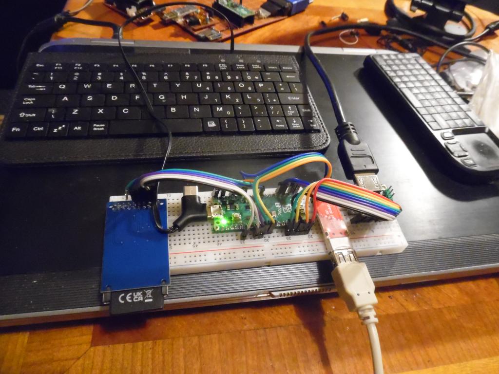 |
||||
| Mixtel90 Guru Joined: 05/10/2019 Location: United KingdomPosts: 8911 |
There isn't really much to understand about HDMI at our level, Stan. You just connect it up, set OPTION HDMI if necessary and use it. Anything magical happens behind the scenes. :) VGA is just the same in use but with a couple less connections and OPTION VGA PINS instead of OPTION HDMI. The only real difference that concerns us is that the position of the pins used for HDMI is fixed. You can't use different GPn pins like you can with VGA. OPTION HDMI simply swaps pairs of pins around out of that fixed group. Mick Zilog Inside! nascom.info for Nascom & Gemini Preliminary MMBasic docs & my PCB designs |
||||
| stanleyella Guru Joined: 25/06/2022 Location: United KingdomPosts: 2807 |
"There isn't really much to understand about HDMI at our level" our level? you know more than I do :) vga is more understandable as it's analogue. it's wiring a vga socket that is a problem for strip/bread board. hdmi more pins you can wave a stick at hence buy dvi breakout board. "the position of the pins used for HDMI is fixed. OPTION HDMI simply swaps pairs of pins around out of that fixed group." where's it show that fixed group and how to set option hdmi pins a,b,c.d ? once set up, as you say, just use it but setting up can be difficult if you don't know how. it seems hdmi gp12 to gp19 are "standard" and option hdmi pins 2,0,6,4 is default as you said. still pins for audio, sd card and usb to ttl PicoMiteHDMI MMBasic USB Version 6.00.00RC15 OPTION SERIAL CONSOLE COM2,GP8,GP9 OPTION FLASH SIZE 4194304 OPTION COLOURCODE ON OPTION KEYBOARD UK, 0, 0, 600, 150 OPTION CPUSPEED (KHz) 315000 OPTION SDCARD GP22, GP6, GP7, GP4 OPTION AUDIO GP26,GP27', ON PWM CHANNEL 5 thanks again for the help or I'd not got board working. stan |
||||
| Mixtel90 Guru Joined: 05/10/2019 Location: United KingdomPosts: 8911 |
Yes, VGA is analogue and HDMI is digital. They are different in that respect bit not so different as you might expect. VGA has the following: Red - analogue Green - Analogue Blue - Analogue Hsync - a logic level that marks the start of each horizontal line Vsync - a logic level that marks the beginning of each frame HDMI has the following: Clock - similar to the clock on I2C D0 D1 D2 - these are digital data channels, each synchronised to the clock. Each of these four signals is a differential pair, like RS-485. That means that they don't have to swing through the full logic voltages so the speed can be a lot faster than normal logic. This is how you get + and - for each signal. It doesn't actually matter to us. We have no control over Hsync, Vsync or the colour channels directly and we have no control over the HDMI signals either. All we see is that we need two additional pins. The HDMI facility hasn't appeared in a manual yet. :) Have a look at my MMBasic Catchup file for 1-11-24. It's on page 17. V6.00.00b4 all versions. It's not fully described in detail though. GP12 to GP19 are *always* the HSTX pins on the RP2350 A and B versions. They are hard-wired to the HSTX peripheral in the chip. They *always* work in adjacent pairs as far as I know. OPTION HDMI lets you select which pair is carrying which signal. Once a pin has been allocated to the HSTX it's no longer a GP pin as it's been disconnected from that section of the chip. It's better to think of them as HSTX0-HSTX7. HSTX0 & HSTX1 HSTX2 & HSTX3 HSTX4 & HSTX5 HSTX6 & HSTX7 OPTION HDMI clockpositivepin, d0positivepin, d1positivepin, d2positivepin OPTION HDMI 2, 0, 6, 4 Puts: CLK+ on HSTX2, CLK- on HSTX3 D0+ on HSTX0, D0+ on HSTX1 D1+ on HSTX6, D1+ on HSTX7 D2+ on HSTX4, D2- on HSTX5 Mick Zilog Inside! nascom.info for Nascom & Gemini Preliminary MMBasic docs & my PCB designs |
||||
| stanleyella Guru Joined: 25/06/2022 Location: United KingdomPosts: 2807 |
Thanks Mick, great info. I'm actually collating info to a folder like MMBasic Catchup file explaining hdmi colours & modes. it's all new stuff for beginners. mmbasic is evolving all the time. I got fed up with soldering vero with single core wire, I'm gonna just solder the pico headers, sd card , usb to ttl and dvi breakout board and use the molex cables and pins. much simpler and tidy if I plan it. I like multi coloured ribbon cable, aesthetically pleasing and makes the boards look clever :) |
||||
| Mixtel90 Guru Joined: 05/10/2019 Location: United KingdomPosts: 8911 |
If you would ever like one of my PCBs just let me know. It's no problem. :) Mick Zilog Inside! nascom.info for Nascom & Gemini Preliminary MMBasic docs & my PCB designs |
||||
| The Back Shed's forum code is written, and hosted, in Australia. | © JAQ Software 2026 |
